Continue to Site

Eng-Tips is the largest engineering community on the Internet

Intelligent Work Forums for Engineering Professionals

  • Congratulations GregLocock on being selected by the Eng-Tips community for having the most helpful posts in the forums last week. Way to Go!

Lateral Earth Pressures on a Deep Rigid Shaft

Status
Not open for further replies.

JSco25

Geotechnical
Dec 15, 2015
8
Hello,

The problem: I have a 40m deep shaft which has an internal diameter of 28m. The proposed construction method is to construct an external diaphragm wall and then excavate internally, to then install an internal pre-cast concrete liner. Diaphragm wall is 1.2m thick, liner is 1m.

My question lies with how to calculate the static and seismic lateral earth pressures which the shaft will experience? Due to the construction method and design of the shaft I have assumed that the diaphragm wall will be non-yielding and therefore an active soil state will not mobilise.
This has left me to calculate the static case based on ko = 1 - sin (phi) and seismic based on Wood and Elms (1990) (attached).

I am also aware of soil arching and its ability to reduce the lateral earth pressures, however, I believe soil arching reduces the stiffer a wall becomes until it is non-yielding and thus static conditions apply.

Any advice on the lateral earth pressures on a 40m deep shaft for the static and seismic case would be very well received!

Many thanks,

 
 http://files.engineering.com/getfile.aspx?folder=90750b02-9997-4e22-bbc0-e8dbc3cbdc3f&file=Wood_and_Elms_-_Rigid_Wall.pdf
Replies continue below

Recommended for you

Considering the magnitude of the project, you haven't provide enough information.
The static earth pressure is a function of long term strain, which is a function of your soil / rock. Do you have a full-depth soil profile (borings and/or CPT)?
Also, what about range of ground water, perched water, and seepage?
 
Hi ATSE,

Thanks for the response. The ground profile is:
0mBGL - 2mBGL - Made Fill (phi = 32, c' = 1kPa, gamma = 15.0kN/m3)
2mBGL - 7.5mBGL - Volcanic Tuff (clayey sand) (phi = 35, c' = 2kPa, gamma = 17.0kN/m3);
7.5mBGL - 15mBGL - Clay (phi = 30, cu = 34kPa, gamma = 17.0kN/m3)
15.0mBGL - 25.0mBGL - Shelly SAND with trace clay. Loose (phi = 28, c' = 0kPa, gamma = 18.0kN/m3);
25.0mBGL - 40.0mBGL - Shelly SAND. V. Dense (phi = 35, c' = 20kPa, gamma = 19.0kN/m3).
Below 40mBGL - Weak sandstone (UCS = 1.2MPa, phi = 40, c' = 140kPa, gamma = 20.0kN/m3).

Water table is at ground surface (0mBGL).

 
Are you planning on dewatering, at least during some parts of the job? What will be your temporary installations, such s perhaps sheet piling in tiers? Any rings for bracing?
 
Oldest guy,
His 1200 thick diaphragm wall would be the first step.
 
Oldest guy has made a reference to this post in the mining engineering section , seeking comments from mining engineers. My comments will not address the OP's initial query but will perhaps provide an alternative solution to the fundamental problem. I have sunk shafts to in excess of 2000 metres deep. By mining standards 40 metres is not deep , indeed even the sandstone bedrock is extremely weak. I suspect that most mining engineers would not have the expertise to do the necessary calculations here, and indeed IF the proposed excavation techniques are practical , it will be a civil or geotech who will have the necessary expertise.

Having said that, previous references to ground water table are homing in on the fundamental problem. These soils are very weak and will wash out rapidly. If this was my project , I would be bringing in the contractors who have experience with ground freezing. 40 metres is not deep for a freezing project, and once the ground is frozen to say 50 metres , excavation takes place in dry conditions and allows for installation of the permanent concrete liner. And yes , 1.0 -1.2 metres of concrete sounds about right.
Hope this helps
 
Prelim calcs to get order of magnitude: K = 0.5 plus full hydrostatic pressure.
An axisymmetric analysis (like Plaxis 2D) with a Hardening Soil material will be useful to run sensitivity analysis, varying the modulus parameters to see the resulting ring compressive force variations.
The limitation is that the actual problem is geometrically axi-symmetric, not the earth pressures and strains don't cooperate that way.
For final design (static) demands a high-powered 3-D analysis.
Seismic may or may not govern depending on your load factors / safety factors, but this requires expert seismic opinion about either pseudo-static (and/or time-history) parameters before you can run your high-powered analysis.
 
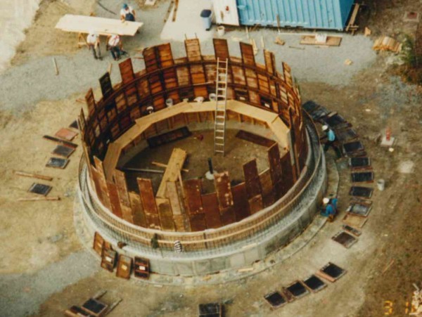
What the OP is describing is a vertical open, cast-in-place caisson. Here is a photo of one in the early stage of construction for an extensive storm water drainage project in Charleston, SC (high water table, high seismic, poor soils)

Casson-1_frgshu.jpg


The cylinder is constructed in lifts, at the ground surface. When a lift is complete, the cylinder's center is excavated allowing a the cylinder to descend a controlled distance under its own weight. The wall thickness is calculated to provide the proper weight to penetrate the upper soils but stop when a firmer layer is encountered. Note that the OP's soil at 40 meters is better than the overburden. Cylinder decent can even be controlled to keep the cylinder plumb by carefully managing exactly how interior excavation is performed.

Here is a brief summary of the Charleston project:

Storm Water Shaft Construction

[idea]
[r2d2]
 
That is one way, SRE, but I wouldn't call that a diaphragm wall. I think the OP means a slurry diaphragm wall, commonly constructed by displacing bentonite in a trench.
 
Hello everyone,
Thank you for the replies and discussion so far.
I will provide a bit more information - I didn't want the original post to be excessively long but cut out some essential info.

The diaphragm wall is a standard bentonite slurry wall construction, reinforced and then tremmied concrete.
Construction sequence summary:
1. Construct diaphragm wall in 28m diameter circle (utilising hoop compression).
2. Excavate internally within diaphragm wall (de-watering as we go due to high water table).
3. During internal excavation install internal concrete liner which is 1m thick pre-cast concrete.
4. Once at 40mBGL install tension piles (shaft is buoyant) and then cast 2m thick ground slab (still de-watering).

The diaphragm wall will be designed for both lateral earth pressures and hydrostatic pressure. The internal concrete liner will only be designed for hydrostatic pressure.

I am heading down the line of performing a 3D Plaxis model of this problem.
I have done preliminary static and seismic calculations based on standard theory. That is that the diaphragm wall is non-yielding and therefore the active soil state of the soil does not mobilise i.e. ko = 1-sin (phi). I have attached some snippets of my calculations for reference. For the seismic case I have utilised Wood and Elms (1990) theory for a non-yielding retaining wall, however, due to the plane strain conditions it was originally meant for I am unsure as to its applicability here.

Miningman - Thanks for the post regarding ground freezing, not sure if it had even been considered.

Regards.
 
 http://files.engineering.com/getfile.aspx?folder=cf66e8f1-594a-4f8c-ae65-7fce4fc2b255&file=Static.PNG
JSco25 - I read the Wood and Elms paper carefully. It appears to address seismic force on a linear wall. Have to wonder if that approach accurately models a rigid cylinder.
I hope what I say next won't get me booted out of this forum [hammer].

As a rough check, perhaps the cylinder could be considered to be a rigid body with the seismic force addressed the old way, as on a dam... in 1934:

"Civil Engineering Handbook", page 806, L. C. Urquhart, 1934

Civil_Engineering_Handbook_egqm3b.png


The value for acceleration used is based on modern references for the project site.


[idea]
[r2d2]
 
Hi SlideRuleEra,

Yes, I agree. That is my major reservation about using that theory is that it was developed for plane-strain conditions.
I have also found subsequent shaft studies which highlight the soil arching effect which can occur. This results in lower lateral earth pressure coefficient. However, 1. I think to fully understand this effect a 3D Plaxis model is required and 2. my assumption here that the diaphragm wall is non-yielding eliminates any soil arhcing effect from occurring. So to move forward my assumption that the diaphragm wall is non-yielding should perhaps change...
 
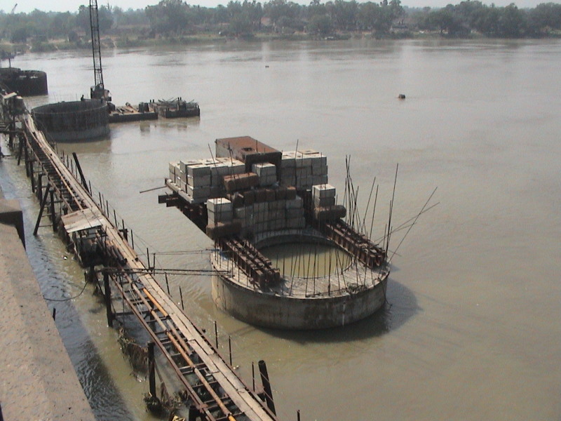
This seems petty complicated . . . I like miningman's thoughts on ground freezing. I know that it has been used many times. SRE actually shows the installation of what they, in India, call well foundations. It seems to me that this might be a better choice than a diaphragm wall, then digging out inside, etc., installing a 28 m liner and then backfiling in between - however as the picture shows there are "dangers" to this although it is used extensively in India.

You might find NN Som and CS Das' book Theory and Practice of Foundation Design, Chap 10 of interest. It explains earth pressures on large diameter "wells" in the ground.
DSC00151_eohxtz.jpg
 
Hello BigH,

Sorry for my delay in responding. Thank you for raising another interesting method.
I have tracked down a copy of the book you recommend and so I will have read. many thanks,
 
Two things need to be noticed in term of diaphragm wall strength and stability.

1, 3D model should be adopted and plane strain analysis is not suitable;
2, the buckling of the diaphragm wall should be investigated under 40 meter hydrostatic pressure
 
Status
Not open for further replies.

Part and Inventory Search

Sponsor