Mike Mike
Structural
- Apr 27, 2019
- 136
What soil spring values would I assign to a finite element model assuming the following:
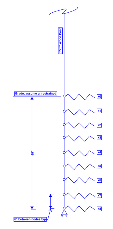
Medium dense sand 120 pcf
Below water table
Friction angle 30 degrees
Assume perfect elastic plastic behavior
Focus on the elastic portion of the p-y curve at k4
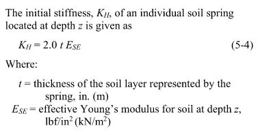
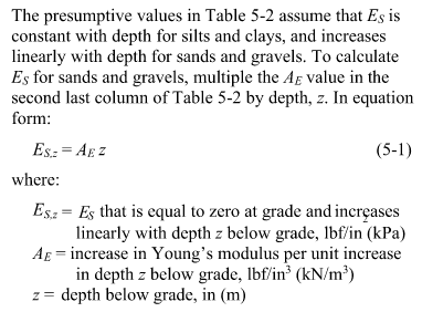
Per the National Frame Building Association Post-Frame Building Design Manual chapter 5, based on ANSI/ASAE EP486.2 (see below), the young's modulus of 55 pci x 24" = 1.3 ksi, for a spring constant k = 2 x t x Es = 2 x 6" x 1.3 ksi = 16 kips per inch. I assume the pole barn method doesn't account for post width because the stiffness is not sensitive to width for thin piles?

I know I should stick to the pole barn manual if I'm designing an embedded wood post, but the curious side of me would like understand the bigger picture and check my results against other methods:
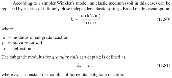
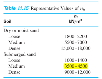
Braja Das Principles of Foundation Engineering (see below) gives 4000 kN/m3, or 15 pci, for constant nh. Multiplying by 24" depth gives a subgrade modulus of 360 psi. I assume since the units are F/L^2, I should multiply by the 6" node spacing, for a spring constant of 2 kips per inch. Seems low. Also shouldn't post width enter into the equations somewhere?
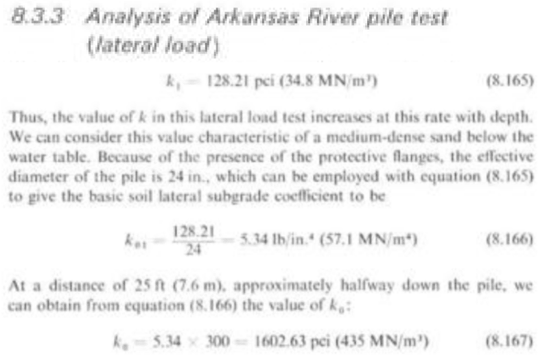
Ronald Scott Foundation Analysis describes soil in terms of advanced mathematics, and does not generally appear offer what I'm looking for, but I believe the section below has some applicability. I assume the basic soil lateral subgrade is 128 pci / 6" = 21 lbs/in4, so the spring constant would be 21 lbs/in4 x 24" x 6" x 6" = 18 kips per inch.
In the thread FixedEarth suggests granular soils actually have a lot of stiffness even near the surface and uses around 50 MN/m3 or 318 kcf, which in our case would result in a spring constant of 318 kcf x 6" x 6" = 7 kips per inch
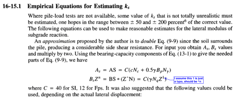
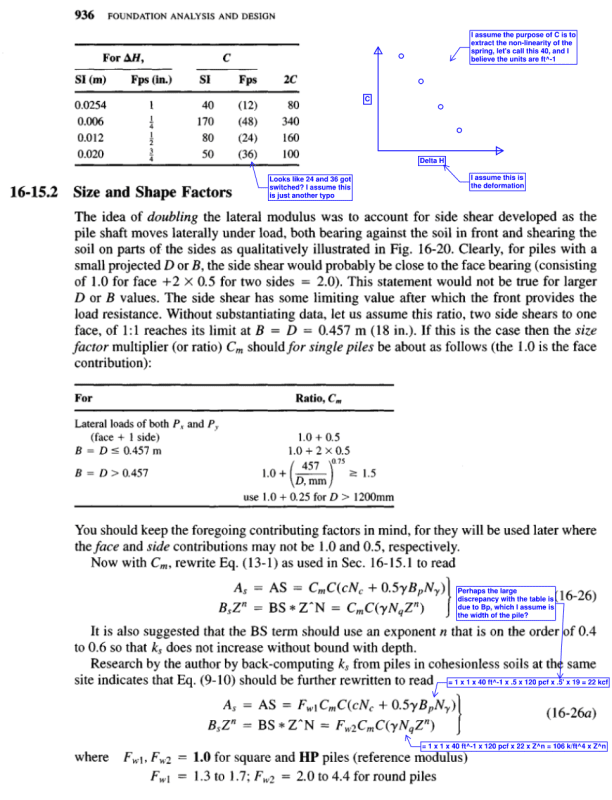
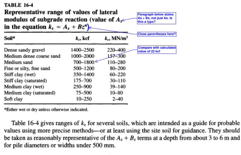
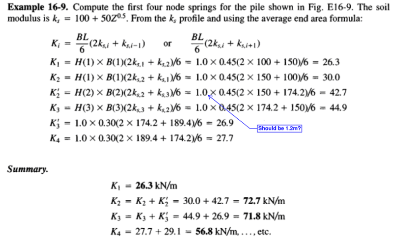
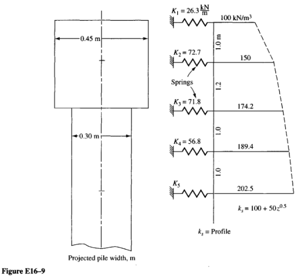
Joseph Bowles Foundation Analysis and Design suggests the following. My markups are in blue. ks = As + Bs x Z^n = 22 + 106 x 2'^.5 = 172 kcf, resulting in a spring constant of 172 kcf x 6" x 6" = 43 kips per inch.
Lastly, I should mention I have designed concrete piles based on borings, with the geotech (not me) reporting the lateral subgrade modulus in F/L^3 for each layer, which I plugged into L-pile software and got reasonable results. I also created a FEM model with spring constants in units of F/L, calculated by multiplying the provided lateral subgrade modulus by the width of the pile and the distance between nodes, and got the same results. Question is, where did the geotech get these magical values? (I'm more of a structural guy, sorry)

Medium dense sand 120 pcf
Below water table
Friction angle 30 degrees
Assume perfect elastic plastic behavior
Focus on the elastic portion of the p-y curve at k4
Per the National Frame Building Association Post-Frame Building Design Manual chapter 5, based on ANSI/ASAE EP486.2 (see below), the young's modulus of 55 pci x 24" = 1.3 ksi, for a spring constant k = 2 x t x Es = 2 x 6" x 1.3 ksi = 16 kips per inch. I assume the pole barn method doesn't account for post width because the stiffness is not sensitive to width for thin piles?


I know I should stick to the pole barn manual if I'm designing an embedded wood post, but the curious side of me would like understand the bigger picture and check my results against other methods:
Braja Das Principles of Foundation Engineering (see below) gives 4000 kN/m3, or 15 pci, for constant nh. Multiplying by 24" depth gives a subgrade modulus of 360 psi. I assume since the units are F/L^2, I should multiply by the 6" node spacing, for a spring constant of 2 kips per inch. Seems low. Also shouldn't post width enter into the equations somewhere?


Ronald Scott Foundation Analysis describes soil in terms of advanced mathematics, and does not generally appear offer what I'm looking for, but I believe the section below has some applicability. I assume the basic soil lateral subgrade is 128 pci / 6" = 21 lbs/in4, so the spring constant would be 21 lbs/in4 x 24" x 6" x 6" = 18 kips per inch.

In the thread FixedEarth suggests granular soils actually have a lot of stiffness even near the surface and uses around 50 MN/m3 or 318 kcf, which in our case would result in a spring constant of 318 kcf x 6" x 6" = 7 kips per inch
Joseph Bowles Foundation Analysis and Design suggests the following. My markups are in blue. ks = As + Bs x Z^n = 22 + 106 x 2'^.5 = 172 kcf, resulting in a spring constant of 172 kcf x 6" x 6" = 43 kips per inch.


Lastly, I should mention I have designed concrete piles based on borings, with the geotech (not me) reporting the lateral subgrade modulus in F/L^3 for each layer, which I plugged into L-pile software and got reasonable results. I also created a FEM model with spring constants in units of F/L, calculated by multiplying the provided lateral subgrade modulus by the width of the pile and the distance between nodes, and got the same results. Question is, where did the geotech get these magical values? (I'm more of a structural guy, sorry)
