skewl
Structural
- Jul 27, 2021
- 46
I am designing a steel box girder with lattice walls due to geometric/constructability/maintenance reasons. The box girder is built in 2 "c-channel" sections with connection plates connecting the two halves at the top and bottom flanges at a set (to be determined) spacing. The box girder spans 30m and cannot be laterally supported at any point along the span.

I have the following questions:
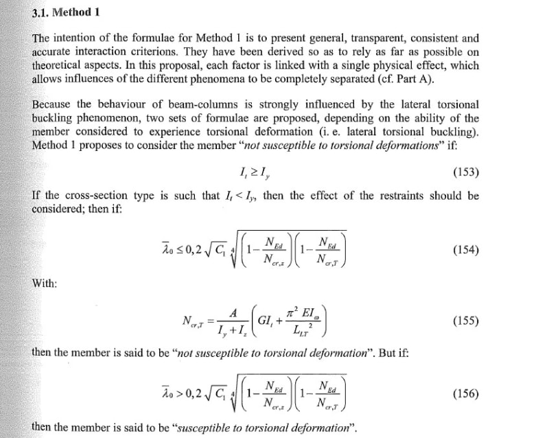
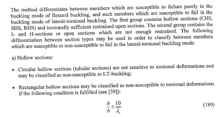
1) Is this section L-T stable?
Closed sections are typically L-T stable, but in this case, there will be "openings" at the top and bottom flanges. I see this as two unstable L-T members laterally braced to each other, and I cannot wrap my mind around how the connected section will be stable (even though my supervisor believes it will be).
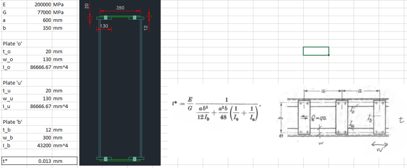
2) How do you evaluate the torsional constant (J) of this section?
The only reference I can find is from "Torsion in Structures (Kollbrunner & Basler 1969)", where a formula is given to find the thickness (t*) of an equivalent plate (see attached PDF). However, the equivalent thickness (t*) appears to be very small.
I have the following questions:
1) Is this section L-T stable?
Closed sections are typically L-T stable, but in this case, there will be "openings" at the top and bottom flanges. I see this as two unstable L-T members laterally braced to each other, and I cannot wrap my mind around how the connected section will be stable (even though my supervisor believes it will be).
2) How do you evaluate the torsional constant (J) of this section?
The only reference I can find is from "Torsion in Structures (Kollbrunner & Basler 1969)", where a formula is given to find the thickness (t*) of an equivalent plate (see attached PDF). However, the equivalent thickness (t*) appears to be very small.
![[sad]](/data/assets/smilies/sad.gif "[sad] [sad]") . You appear to be correct and this solves my issue with the torsional properties.
. You appear to be correct and this solves my issue with the torsional properties.