Continue to Site

Eng-Tips is the largest engineering community on the Internet

Intelligent Work Forums for Engineering Professionals

  • Congratulations KootK on being selected by the Eng-Tips community for having the most helpful posts in the forums last week. Way to Go!

Lateral Torsional Buckling of Coupled Channels Beams 1

Status
Not open for further replies.

jiejingzhou

Structural
Aug 19, 2016
3
Hello Everyone,

I just have a general regarding LTB for a coupled double channel:

If two simply supported channels are spaced quite far apart, say >=5", and they are connected only using vertical stiffeners/diagram elements at every X ft o.c.


1) Is the unbraced length for LTB the entire span or the stiffener spacing X

2) For calculating rt and rts, the effective LTB radius of gyration per AISC

rt = bfc/sqrt(1 + aw/6)

do you take bfc to be that of two channels or one?

I guess what I'm really looking for is to what extent should the two channel be connected such that in act as one unit for LTB.

Thank You!
 
Replies continue below

Recommended for you

They need to be connected such that they resist horizontal shear across the combined section, be it in the longitudinal direction or transverse.

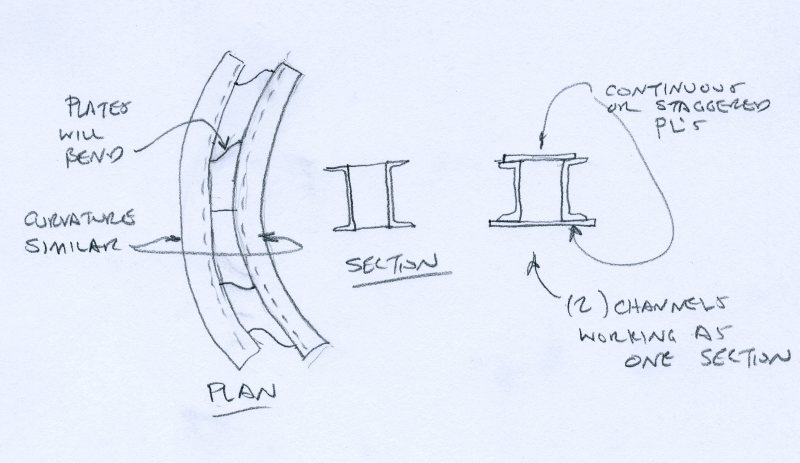
Since you only have vertical plate stiffeners between them, the stiffeners can bend such that the channels will act as two separate channels.
They will bend and deflect and laterally buckle together, but their resistance to that buckling is simply the sum of two channels...not a combined "I" beam or box shape.

Now if you provide horizontal plates across the flanges - making essentially a box shape, then you can resist the horizontal shear produced between them and you have a much higher resistance to LTB.

Channels001_sl3v6h.jpg


Check out Eng-Tips Forum's Policies here:
faq731-376
 
OP said:
I guess what I'm really looking for is to what extent should the two channel be connected such that in act as one unit for LTB.

For LTB, I don't know that there's a simple parameter that can be used for this like there is with built-up columns. You may just have to calculate the flexural capacity based on the single channels at the fastener spacing and ensure that it's greater than the capacity of the composite section flexural capacity.

Determining the overall, composite section capacity is a tricky business as JAE intimated. You could take either of these paths:

1) Try to make the channels function as a true composite section. While my gut feel is that the vertical plates, at a reasonable spacing, would probably get the job done, it's not an easy thing to prove with certainty. If you want to go this route, I'd recommend applying methods similar to those found in this paper which deal with the stitch welding of built up columns.

2) Create a lower bound estimate of the flexural capacity. Treat it as a wide flange beam with these properties:

Iy = 2 x Iy (single channel)
J = 2 x J (single channel)
Cw = 2 x Ix_single x (distance_between_shear_centers / 2)^2

I like to debate structural engineering theory -- a lot. If I challenge you on something, know that I'm doing so because I respect your opinion enough to either change it or adopt it.
 
If you really want to (need to) get into it, and can use horizontal/"batten" plates, this paper has been useful to me in the past.


But, it still will be iterative as KootK suggests, and certainly cumbersome. If you can get away with a lower bound solution, that's probably for the better.
 
I largely agree with JAE. As you've descrived the section, they can't act together to resists warping or torsional stresses, so those are the algebraic sum of the properties of two channels. I think you can make a case the combined section will act together laterally though, and use a composite I.y, depending on the strength of the connection between them.


Thank you everyone for the great feedback. After giving some thoughts into it, here is what think, please feel free to correct me.

@JAE, if the buckling mode is weak axis flexural buckling, i think you are completely right about adding horizontal batten plates, they plates need to resist shear and moments to force the two members act as one,

however, i think when buckling mode involves any type of torsion (TB or LTB), then vertical stiffeners (provided they are closely spaced) should be able to link the two members. (i.e. the stiffeners impose a rotational constraint) -> I'd like some more feedback on this

Here is my approach to this issue, which is similar to @KootK's suggestion:

1. Take rt = 2 x rt single channel (AISC)
2. Take J = 2 x J single channel
3. Take Cw = 2 x Cw single channel

Calculate LTB capacity based on the properties mentioned above

Individual member LTB will not govern due to close stiffener spacing.

Thanks!
 
getting in to weld vertical stiffeners with a 5"+/- gap would be tough, especially as the channels get deeper. the horizontal plates would be much easier.

Also, see the attached paper - its about I shaped sections but channels should be similar.
 
 http://files.engineering.com/getfile.aspx?folder=7932908c-ae7e-470b-83bf-783d66509035&file=Global_Lateral_Buckling_of_I_shaped_Girder_Systems.pdf
If the vertical stiffeners bend as per my plan view diagram, there will be relative movement along the length between common points on the two top flanges.

Thus, the two top flanges may also have different deflections laterally relative to one another and the rotation angle of each channel could be different.
If the rotation angle is different then they aren't behaving as a complete composite, locked-in shape but rather two shapes that are connected together in a semi-rigid mechanism.

As KootK stated, determining the LTB performance of these channels with vertical plates and a semi-rigid relationship is "tricky"....in other words, it would take more time than its worth.


Check out Eng-Tips Forum's Policies here:
faq731-376
 
I can't see the plates bending like that... it would take an exceptional amount of force between the two channels to yield them. In fact, if you use staggered plates to make a box section, you're actually even weaker with respect to bending in that manner.
 
What about coupling them with tube steel sections? They would provide lots more composite action than vertical plates.
 
canwesteng - it depends on the span of the channels and the thickness of the plates. If the plates are 1" thick then yes, they may not bend as much.

With a 20 ft. span, heavy loading, and 3/16" stiffeners at 48" o.c. I can certainly see these wet noodles bending.

Check out Eng-Tips Forum's Policies here:
faq731-376
 
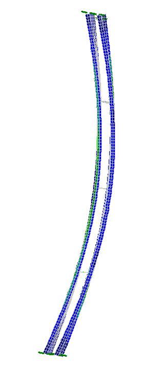
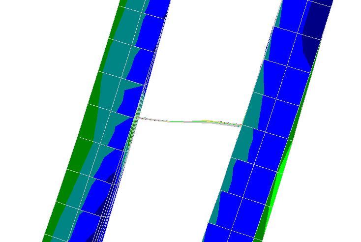
Here's a few images of a quickie model I made:
C10x15.3 channels spanning 20 ft. with a 6 inch gap between them and 1/4" plates @ 5 ft. o.c. between them.

An overview of the two channels:
Model_Overview_p1illd.jpg


A close up of one of the end plates with a deformed bend in it: (note the bend is as I've drawn it above)
Model_detail_at_plate_nj6bf1.jpg


Check out Eng-Tips Forum's Policies here:
faq731-376
 
Also a close up of a rendered view:

Model_rendered_at_plate_x3gzow.jpg


Check out Eng-Tips Forum's Policies here:
faq731-376
 
Status
Not open for further replies.

Part and Inventory Search

Sponsor