I have a 5"x27" glulam beam (very slender) spanning 35'. The compression side of this beam does not have any lateral support, and as a result, the beam fails in bending. I've calculated that in order for this beam to work, the compression side needs to be laterally braced at third points along the beam. What I'm not sure about is how much load those braces need to be designed for. I can't find any guidance on how to determine the lateral bracing load for timber beams. I know that for steel beams, the lateral bracing load is based on a percentage of compression load in the flange (usually about 2%). But in the case of a glulam beam like this, there are no flanges, so I'm at a bit of a loss. Even if there were flanges, I'm not sure the same rule that works for steel would also be appropriate for timber. Any suggestions? Thanks in advance.
Navigation
Install the app
How to install the app on iOS
Follow along with the video below to see how to install our site as a web app on your home screen.
Note: This feature may not be available in some browsers.
More options
Style variation
-
Congratulations cowski on being selected by the Eng-Tips community for having the most helpful posts in the forums last week. Way to Go!
You are using an out of date browser. It may not display this or other websites correctly.
You should upgrade or use an alternative browser.
You should upgrade or use an alternative browser.
Lateral torsional restraint of glulam
- Thread starter JIMEY
- Start date
- Status
- Not open for further replies.
Greenalleycat
Structural
I've never calculated it for timber but also have never really thought about it
With timber typically being rectangular cross-sections I think your load-applying element usually also gives you support
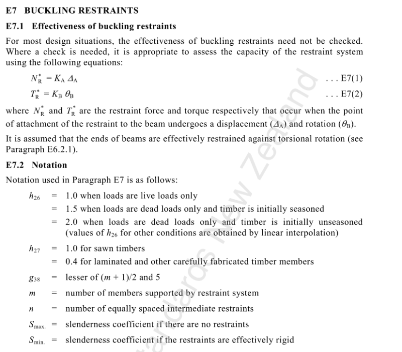
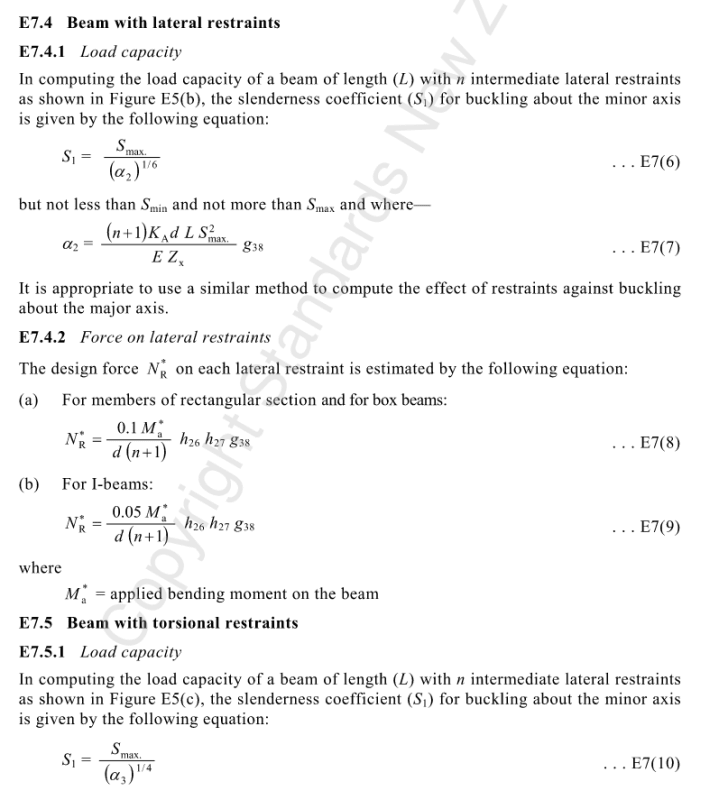
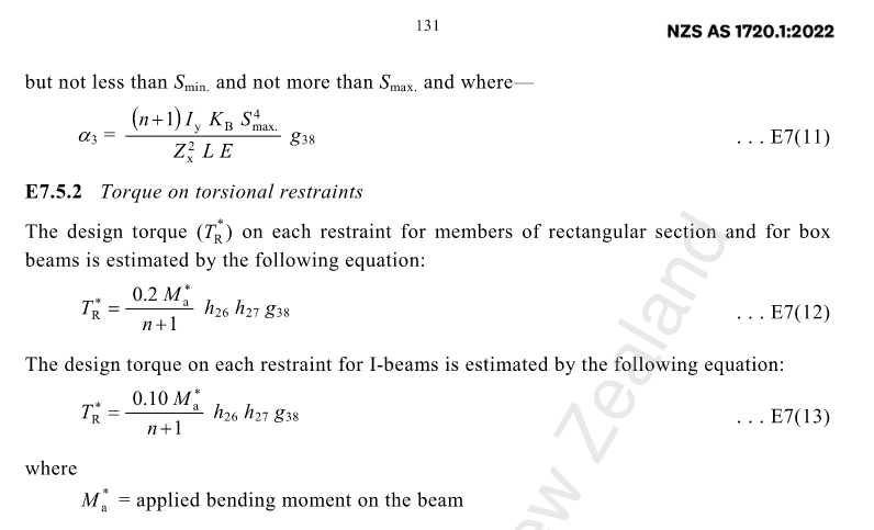
But I've looked into our code for interest and have snipped the relevant bits below for you to take a look at
Effectively, it says that you don't normally need to calculate it, but here's a really complex looking way to do it if you want to
Good luck

-----------------------------------------------------------

-----------------------------------------------------------

With timber typically being rectangular cross-sections I think your load-applying element usually also gives you support
But I've looked into our code for interest and have snipped the relevant bits below for you to take a look at
Effectively, it says that you don't normally need to calculate it, but here's a really complex looking way to do it if you want to
Good luck

-----------------------------------------------------------

-----------------------------------------------------------

SWComposites
Aerospace
Jimey, can you show a sketch (embedded image) showing how this beam is installed and loaded?
- Thread starter
- #5
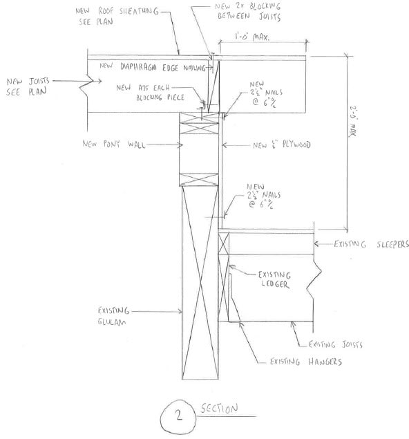
Thank you all for your help. I think I found the answer I was looking for. Eurocode 5 Part 1-1 has a section 9.2.5.2 which gives the load that lateral bracing for timber members (including beams) should be designed for. But if anyone is still interested, I've attached a link to a sketch showing my exact situation.
It's a bit of a judgment call I suppose, but I think most engineers would consider the existing framing as providing acceptable lateral bracing of the glulam, despite it not being exactly at the top. I have trouble picturing the beam failing in lateral torsional buckling with that framing there. In terms of the buckling restraint force, I wouldn't normally calculate that, but if I did, I'd probably use 2% of the compression component of the moment.
Your sketch (for convenience):

Your sketch (for convenience):

Alistair_Heaton
Mechanical
Norwegians are doing some research on a broad spectrum of issues with glulam.
Think it's link to the bridge collapses.
Think it's link to the bridge collapses.
- Status
- Not open for further replies.
Similar threads
- Locked
- Question
- Replies
- 15
- Views
- 6K
- Locked
- Question
- Replies
- 6
- Views
- 3K
- Locked
- Question
- Replies
- 3
- Views
- 952
- Locked
- Question
- Replies
- 4
- Views
- 1K
- Replies
- 12
- Views
- 6K
