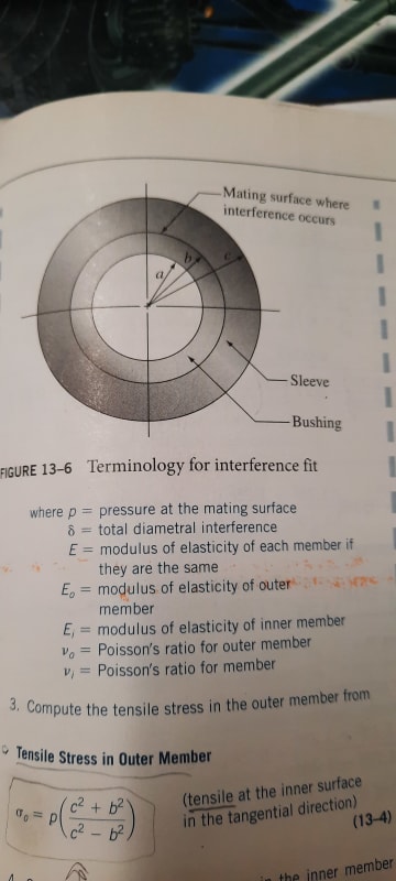
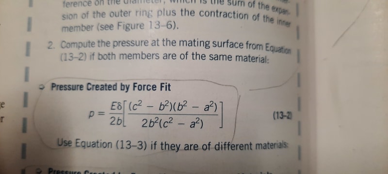
I am trying to find a formula that will determine pressure at the mating surface where the housing/spring eye is open and not welded shut into a bore. Both materials are steel. I would think it would have to incorporate perhaps a spring constant or the something similar? I could not find anything in any of the design books I own.
Navigation
Install the app
How to install the app on iOS
Follow along with the video below to see how to install our site as a web app on your home screen.
Note: This feature may not be available in some browsers.
More options
Style variation
-
Congratulations TugboatEng on being selected by the Eng-Tips community for having the most helpful posts in the forums last week. Way to Go!
You are using an out of date browser. It may not display this or other websites correctly.
You should upgrade or use an alternative browser.
You should upgrade or use an alternative browser.
Leaf spring press fit
- Thread starter fortjp500
- Start date
- Status
- Not open for further replies.
hi fortjp500
I am not understanding exactly what you are trying to do, can you provide a sketch?
I am retired now but during my working career I used to design small leaf springs etc so I might have something that can help.
“Do not worry about your problems with mathematics, I assure you mine are far greater.” Albert Einstein
- Thread starter
- #3
- Thread starter
- #4
The formula shown would be useless as soon as one would make a cut in the outer housing as it would no longer be attached (like a leaf spring eye is). I want to calculate the mating surface pressure which I can then use to determine the stess in the outer member.
Hi
Right I see now what you are trying to do and yes you would need the spring stiffness for the outer ring. How big a cutout are you going to make? I would think if the cut out is very small and the inner ring O.D. Was still larger than the I.D. Of the outer ring the equations might give you a good approximate. When you were talking of leaf springs I thought you meant small thin gauge material like 0.5mm thick.
“Do not worry about your problems with mathematics, I assure you mine are far greater.” Albert Einstein
BrianPetersen
Mechanical
Normally what's pressed into that open eye is a bushing with a thin outer steel sleeve with the rubber bushing inside it (bonded/molded+cured in place). The outer sleeve of the bushing assembly is not perfectly rigid and will conform to the shape of the inside of the spring eye.
- Thread starter
- #8
I hadn't thought of it as a curved beam with a rectangular cross section but that would be the case for sure. If I know the inner diameter of the spring eye and the outer diameter of the bushing that will be interfering, is there a way to get to stress from there using the moment equation perhaps? Sigma internal= M/eA * (ci/ri)
I don't know the Moment that would result from an interference fit? Is this the correct thought process?
I don't know the Moment that would result from an interference fit? Is this the correct thought process?
BrianPetersen
Mechanical
It is a statically indeterminate situation that has to be resolved using deflection. The spring eye will be deflected to a larger diameter, the bushing will be compressed to a smaller one ... except that it won't be uniform deflection, because the outer shell of the bushing doesn't have uniform pressure on it all the way around ... because of that gap in the leaf spring eye. And, if that bushing is the normal design (steel outer shell with rubber/urethane inside it), the bushing itself is a non-uniform construction.
Why do you need to attempt to analyse this so precisely?? You won't be able to ...
Why do you need to attempt to analyse this so precisely?? You won't be able to ...
- Thread starter
- #10
GregLocock
Automotive
The only useful equation with beams is M/I=E/R=s/y. So in your case you need to know the yield stress s, the spring thickness 2y, the Young's modules. then you get the change in curvature 1/R, at yield.
Cheers
Greg Locock
New here? Try reading these, they might help FAQ731-376
Cheers
Greg Locock
New here? Try reading these, they might help FAQ731-376
- Thread starter
- #12
I get that yield stress = E * y/ neutral axis. I don't understand what y is and how it relates to diametral deflection. For example if I am installing say a 1 inch radius rod into an eye that has an undersized inside radius of say 0.975" that would be diametral interference of 0.050". If the spring wall thickness is 0.25" then that puts the neutral axis at r = thickness/Ln(outer radius/inner radius) = 1.0952". I don't understand how to determine y and it's significance.
GregLocock
Automotive
You need to look at beam theory. y is the distance from the neutral axis to the extreme fibre of the section. The relevant part of that equation is just the definition of E and a bit of geometry.
Cheers
Greg Locock
New here? Try reading these, they might help FAQ731-376
Cheers
Greg Locock
New here? Try reading these, they might help FAQ731-376
thing is that the neutral axis shifts when the beam has a very pronounced curvature, which brings you back to curved beam theory. You can apply straight beam theory to a curved member as an approximation, but the more pronounced the curvature is the less accurate it becomes. It would basically be a curved beam with a uniformly distributed load on the inside curvature (If I've got this thing pictured correctly). It's gonna take some figuring out though.
- Status
- Not open for further replies.
Similar threads
- Replies
- 16
- Views
- 4K
- Replies
- 8
- Views
- 2K
- Replies
- 15
- Views
- 5K
- Question
- Replies
- 4
- Views
- 13K
- Replies
- 3
- Views
- 1K


