Eng-Tips is the largest engineering community on the Internet

Intelligent Work Forums for Engineering Professionals

Learning Programming for Structural Engineering 12

Status
Not open for further replies.

MegaStructures

Structural
Sep 26, 2019
366
0
0
US
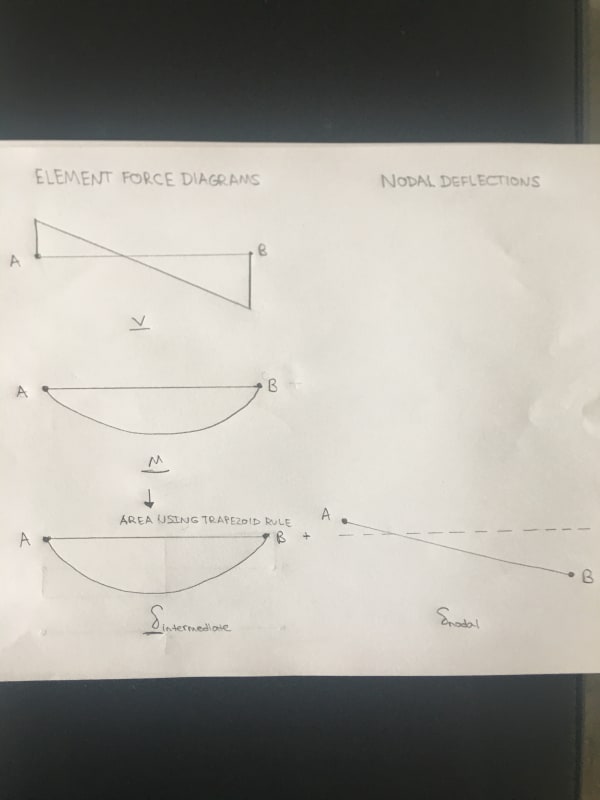
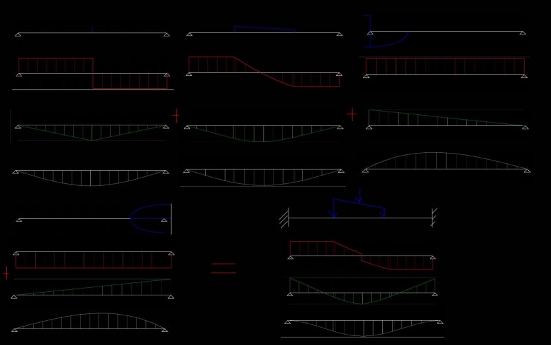
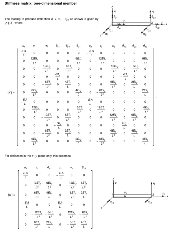
I have recently become very interested in matrix structural analysis and finite element analysis and I have been creating my own "program" using excel. Of course I have quickly noticed that the basic operations available within excel without using VBA is somewhat limited and I cannot make the quality of the program I want. So naturally I have began learning VBA and in my journey around the internet learning VBA I have seen other recommendations for more powerful languages such as Python, Matlab, Fortran etc..

During this whole process I have been thinking a lot about the usefulness of coding in structural engineering and thought that it might be a fun conversation to have to see what other structural engineers have taught themselves to code, how useful they have found it, and what language might be the most helpful. So I would love to hear others opinions on the topic of coding for a structural engineer!

“Any idiot can build a bridge that stands, but it takes an engineer to build a bridge that barely stands.”
 
Replies continue below

Recommended for you

My apologies IDS, I asked about the method used to find deflection on your beam program, but I meant to ask about the Frame4 file, since I’m building a general frame program now. For now I have been trying to use the double integration method by creating sample points at every 0.25” of beam length and obtaining values for shear and then calculating the approximate area under the curve with the trapezoid rule to find moments, slopes, and deflections, I figure I can always tighten up the distances and make the result more accurate, since I can’t think of a way to get an exact equation to integrate. (So this is the simple beam portion of your example above)

The last thing I am still trying to figure out is how to deal with end conditions on my deflection values, which I think you gave me the answer to above, but I just haven’t quite grasped the concept. I of course already have nodal deflections calculated for purposes of finding element forces, but I have to figure out how to make the intermediate deflection results and nodal deflection results “agree”. I’m just not quite grasping the idea of making a system of equations, because I’m not working it through equations, but a set of approximated points. Of course equations would be better if I could figure out how to create them :)

“Any idiot can build a bridge that stands, but it takes an engineer to build a bridge that barely stands.”
 
Mega:

You can create the Shear, Moment, slope/rotation, and Deflection equations for each load type using direct integration, doing it this way you can greatly reduce the number of stations to just what you need for a smooth plot and avoid the compounding error of approximate integration routines (I found this to be about 20 to 25 stations along the span).

Once you have these, or you can take them from my github here: Link, then at each station you can calculate the desired result per load type and add them together, superposition, to form the total response.

To account for end deflections you can again use superposition and either do linear interpolation between the two nodal deflections or form the line equation and get a direct result.

For getting exact results see this thread where I struggled/overcomplicated the process:
My Personal Open Source Structural Applications:

Open Source Structural GitHub Group:
 
VBA version of the beam formulas I posted here, 01 - Beam_User_Functions file and the three .bas files: the .bas files are exports of the VBA while the excel file has them loaded in as User Defined Functions (UDFs)

Quick note when I derived these formulas it was before I started getting into stiffness methods so the sign convention doesn't follow what you'll see in textbooks for that method.

My Personal Open Source Structural Applications:

Open Source Structural GitHub Group:
 
Ah I think I get it! There are intermediate deflections caused mainly by the internal moments along the beam span, which can be found by integrating the moment (I chose the trapezoid rule to do this previously) and there are nodal deflections found from the stiffness matrix solution. A unique beam deflection can be found by each case at discrete stations and then combined to form a final deflected shape. The only thing I haven’t taken into account with this explanation (I think) is the effect of moment constraints, which will hold slope=0 at the boundary and should be reflected in the deflected shape. My first thought to show this is by putting an if statement in the first 2 stations of the Intermediate deflected shape that basically says if the node is fixed against rotation the first two stations deflection should be 0 (maybe I would have to adjust how many stations to add this condition to based on how it made the plot look)

“Any idiot can build a bridge that stands, but it takes an engineer to build a bridge that barely stands.”
 
image_hpolgj.jpg


“Any idiot can build a bridge that stands, but it takes an engineer to build a bridge that barely stands.”
 
Superposition of the individual results of the direct functions for V,M and D for a point load, trapezoidal load, left end moment, and right end moment. (moments used here correspond to the fixed end moment so the start and end slope of the deflection curve is 0)

Image001_iqjbsv.jpg

(link to larger image: here)

My Personal Open Source Structural Applications:

Open Source Structural GitHub Group:
 
Celt83 I was hoping I got back to the post before anyone else did. I was doing something else and it popped into my head how silly I was with my struggles on how to include the deflection from a fixed end. Of course the reaction moments at fixed end will result in another shear-moment diagram that can be integrated to find the deflection and then superimposed. Your picture makes it even clearer and I can’t wait to add intermediate deflections to my program.

Thanks to all!

“Any idiot can build a bridge that stands, but it takes an engineer to build a bridge that barely stands.”
 
MegaStructures said:
shear-moment diagram that can be integrated
I still recommend not doing numerical integration via trapezoidal or Simpson rule and instead come up with the actual slope and deflection formulas for end moments or more generally for a moment applied at any point on the beam.

Formulation of those slope and deflection formulas are actually the foundation for the stiffness matrix that your using so would be a good exercise anyway. The bending stiffness entries in the matrix come from solving the simultaneous equations for introducing unit slopes and deflections to either end of the beam.

My Personal Open Source Structural Applications:

Open Source Structural GitHub Group:
 
not sure if your working off of any textbooks for reference but here are a couple good ones:

Matrix Analysis of Framed Structures, Gere : Moment Distribution, Gere: (This one is a great pre-cursor to matrix analysis to build up a foundation on member end flexibility/stiffness)

Mastan2: (this one is free and so is the associated program, goes into advanced analysis for second order effects and buckling)

My Personal Open Source Structural Applications:

Open Source Structural GitHub Group:
 
@OP

In my opinion, programming is great skill to pick up as a structural engineer. The best thing about learning programming is that it will teach you more about structural engineering. When you write a program to solve a structural analysis problem, you aren't solving a single geometry which is typical for project work but a field of problems.

That process will force you to learn the edge cases in structural analysis which most engineers don't get to see in the same way. It gives you this holistic view, where you'll be able to see issues other engineers who have always approached the problem with a "just get it to work" mentality don't.

For my two cents, I agree with @captain_slow. I really like python. Easy to learn but extremely powerful if you choose to go further with it. Numpy and scipy are great for optimisation, but then can also learn FEM APIs. It's also worth noting that python is the language of choice for machine learning / AI which, full disclosure I think is a a long way off from having an impact in structural engineering, but that only means you could be the engineer to create that impact.

Hope that helps.


Complete Columns
 
@IDS,

I am the first person to admit that choice of programming language depends on the type of problem at hand. VBA has its ups and downs with the ups being Excel integration and how commonplace it is (certainly more commonplace in structural consulting than any other language) and the downs being cryptic syntax and lack of in-built array functionality. I personally die a little inside every time I have to juggle/loop/sort arrays in VBA.

I think that the following is a good example of how choice of language depends on task at hand.

My workplace uses RAM Structural System as our main FEA package. RAM SS has a decent enough FEA engine and an outdated user interface that lacks a whole heap of modelling features. In short, if I have to model a large structure in RAM I am not happy with life until modelling is done and I get onto post-processing of analysis. However RAM SS also has an application API - this serves as a back-end way for me to talk to the application programmatically and enables me to program a few features that I lack. I have a choice of C# or VBA to access the API from which I choose VBA because I am functional at it. This also has an added benefit of my code being maintainable when I move onto a different workplace as my office has two other guys that know VBA and nobody that is familiar with C#.

On the other hand when I come home I want to run some statistical analysis based on scraped web data (non-engineering related side hobbies) I use Python. Python enables me to do pretty much anything and everything - I can scrape data from the web, I can juggle enormous arrays of information, and I can perform fancy analysis using dodgy (and non-dodgy too) pseudo-AI libraries that I download from GitHub. Trying to do all of this stuff with VBA would be like sawing timber with a kitchen knife, theoretically possible but why would you do it if there are better tools available.​

This is not criticism of VBA as a language at at all - I think that it does its job very well. It's just a fundamentally different beast to Python and so there is little use in comparing the two. Hence my advise to new programmers is typically to learn Python if they want to learn programming and to learn VBA if they want to boost their employment value.

And I also always say to not ever expect anything employment wise from being able to code. We are structural engineers and so we are typically hired for the task - employers seldom set out to find a structural engineer that can code, they are typically more interested in your ability to structurally engineer.
 
@Complete_columns,

Mostly agree with everything you say - especially the "edge cases". Engineers have a weakness for falling into "just get it to work on paper" type of situations, which is a complex professional issue deserving its own thread.

I just want to say that I really like your website - had a glance at it a few days ago and it looks very good. Certainly very impressive visually. Having said that I am yet to dig properly into it and look at content as time is always short...

Having had a brief read through some of the information I notice that you have some sizing optimisation features - I may or may not contact you for a chat about that if you don't mind as this question of efficiently grouping structural elements has been dwelling on my mind lately. But that is once I look properly through your website lest I say something silly.
 
@OP,

For a beam element FEA solver you have to work with generic formulas for beam deflections under generic loads. This is a complex topic, however I reckon I can give you the generic stiffness matrix:

Screenshot_2020-10-04_at_19.32.50_xtl0wd.png


Generally speaking you have to do the following:

1. Discretise your load.
2. Discretise your beam.
3. Generate a load vector and assemble a corresponding corresponding stiffness matrix.
4. Solve the resulting matrix equation for the displacement vector.
5. Post-process and derive moment/shear/displacement diagrams.​

You certainly need to discretise a bit further than 4 sub-elements to get accurate solutions - ideally you make number of sub-elements an input into your function and then you can vary that number to see how number of sub-elements affects accuracy of your solution.
 
@captain_slow

Thanks very much. It's a work in progress but that's exactly what I was going for. Column design grouping optimisation through visualisation rather than a black box algorithm. Also a pretty picture to impress clients.

Please do follow up if want to chat. I'm at nick@completecolums.com.

And I may have to start that thread about where engineers sit on the "just get it to work" versus "read everything about the problem" scale.


Complete Columns
 
captain_slow said:
You certainly need to discretise a bit further than 4 sub-elements to get accurate solutions - ideally you make number of sub-elements an input into your function and then you can vary that number to see how number of sub-elements affects accuracy of your solution.

You really don't need to sub divide the bar elements. If you have the general formulas worked out all you need is the end moments and you can then construct the full piecewise formulas for shear, moment, slope, and deflection and solve for the roots to find locations of absolute maxima and minima. With the piecwise formulas worked out you can then just take a sampling of stations along the bar so when you plot the diagrams they look nice enough, you can speed up the backend a bit by doing the station values on demand when showing the plots vs preprocessing them and having them stored in memory. When you plot inject additional plot points just before and after load points this gets the discontinuity in the shear/moment diagram shown with a nearly vertical line vs diagonal line with uniform spacing of your reporting points, also inject the root points.

My Personal Open Source Structural Applications:

Open Source Structural GitHub Group:
 
Sub division would be import if you are planning on performing a natural frequency, transient and non-linear analysis. Even if you are applying loading based on piece-wise functions, you can attain a solution using Laplace transforms coupled coupled with a coarse stiffness matrix...


@Captian_slow, I completely agree with you... Everything has it's place for a particular task. I've actually seen some engineers spending an entire day doing FFT on excel, when you could do something like that in a few lines of code of the right language.

It is good practice to research the tools available before just jumping in and developing something.
 
@RFreund

I have not used MathCad, however it seems to be a completely different animal to Octave.

I have not really bothered with GUI's when developing programs. By reports I assume that you mean an actual written aspect showing equations, results and discussion which is the output? If so, I don't, it seems that MathCad has a nice interface for that and the newer version of Matlab have incorporated that aspect.

I generally have graphs which are developed which I then paste into my design reports, as the reports will cover information from a number of places.

In cases where my code is used by a few people in the office, I generally have a manual for it's operation as it may be a bit confusing entering information within the code itself. It's a poor way to do things though, I wish I had the time for GUI's.
 
Status
Not open for further replies.
Back
Top