Phuduhudu:
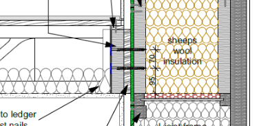
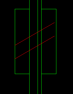
In some fashion, the structural screws/lag bolts are cantilevering out from the primary structural beam/inner rim board to carry your ledger beam. And, they pass through several layers of materials of questionable structural integrity. I would prefer cutting the battens off/out so that the ledger beam can bear tight up against the OSB; even better, cut the OSB out too, so the ledger bears directly against the primary LVL beam. Draw a FBD of that screw, it needs a certain penetration into the primary LVL beam just for tensile holding power, and generally discounts the first .25" +/- of length at its tip. Then it cantilevers outward off that primary LVL beam. At each of the outer mat’l. layers this canti. is supported by a spring reaction at the OSB and at the battens and finally loaded downward at the ledger beam. At each layer there may be some slop in the screw hole sizes and there may be some bearing crushing when the screw is loaded. Thus, there can be considerable vert. movement in the total joint as the number of layers increase, it is difficult to pin down how much each layer carries/supports (its stiffness as the spring reaction) and worst off all, the canti. length increases too. I think their admonition about the number of shear planes (faying surfaces) relates mostly to the above issues, certainly the screw is not stronger because it is in double shear, or some such. Finally, it is just tougher to draw the total joint tight, with screw tension, as the number of layers increases. Take a look at the AF&PA Design Guide #6, “Prescriptive Residential Wood Deck Construction Guide,” it has some good detailed discussion on ledger beams and screw locations in them (spacing, edge dist., etc.). Most good wood design texts cover these subjects too, but I doubt that you will find anyone giving you the spring stiffnesses for those screw canti. reactions. That’ why they say/imply..., get the ledger right up against the primary beam, by saying not several shear plains away.