Eng-Tips is the largest engineering community on the Internet

Intelligent Work Forums for Engineering Professionals

  • Congratulations waross on being selected by the Tek-Tips community for having the most helpful posts in the forums last week. Way to Go!

Lever Arm for Stiffened End Plate Moment Connection 1

Status
Not open for further replies.

Blackstar123

Civil/Environmental
May 5, 2013
253
US
Follow up question from thread507-220851

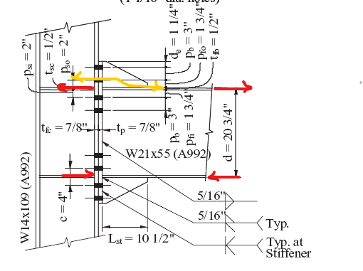
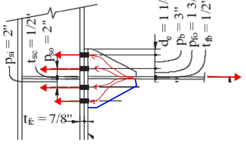
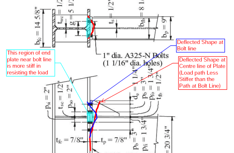
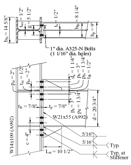
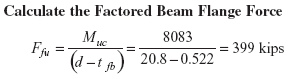
Situation describe in referenced thread is somewhat similar to at AISC design example 8ES. Contrary to believed opinion of most contributors, lever arm consider in this example to determine the couple force is d-tf, even though the end plate stiffener is sized to prevent local buckling. I came looking for answer here because I am of the same opinion that lever arm should at least be considered from beam compressive flange to the centroid of the tension stiffener. However, code document suggest otherwise. In this kind of contradictory situation would you follow the code example or your own understanding?

image_wttmr3.png


image_qfcpyt.png
 
Replies continue below

Recommended for you

Your opinion is correct only if the upper flange has not welded to the end plate, the force therefore has to find a path (in yellow)to get to the support. Otherwise, force vector occurs straightly through the shortest path between two points.

image_bonxrr.png
 
Blackstar said:
I came looking for answer here because I am of the same opinion that lever arm should at least be considered from beam compressive flange to the centroid of the tension stiffener.

I disagree. Once you provide the four rows of tension bolts, I think that it's reasonable to assume that the center of tension for the connection is at the centroid of that bolt group +/-. It'll be a little higher owing to the linear strain profile acting across the connection. Moreover, if you've got the stiffeners in the column, the bolts immediately above and below the stiffeners will be the stiffest load path of the bunch which, again, leads to the as assumption that the tension acts at the level of the tension flange.
 
As I understand it, the couple force and its lever arm depends on the weld provided to transfer the force from beam to end plate. For example, if let’s say that the beam is connected to end plate through end plate stiffener welds only, than the couple force will approximately act at the center of stiffener welds.
Following the same line of reasoning, isn’t it logical to consider the contribution of welds at end plate stiffener to resist the end moment?
 
isn’t it logical to consider the contribution of welds at end plate stiffener to resist the end moment?

Yes, if the beam flange to end plate connection alone is not enough to take the load, then the stiffener will have to contribute. But usually it wouldn't be the case. If you purposely design the weld of the stiffener to take some load, there runs a risk that the beam flange weld is under sized, and the joint will break apart under full load before the weld of stiffener feels the stress.
 
Blackstar123 said:
Following the same line of reasoning, isn’t it logical to consider the contribution of welds at end plate stiffener to resist the end moment?

The welds are considered. They're considered as part of the load path distributing 1/2 of the load to the end plate above the flange and the other half, by similar reasoning, to the end plate below the flange.

In the sketch below, I've stripped away the parts of the beam unnecessary for transfer of the tension flange force. Do you have any reason to think that the centroid of that force wouldn't be transmitted to the column at the level of the top flange? I would argue that this is substantially the same situation.

If you want the effective lever arm to be above the flange, you may have to remove some or all of the bolts immediately below the flange.

C01_fklse3.jpg
 
I agree with taking the centre of the upper bolt group as the tensile force centroid.


In reality the tensile centroid might be a bit higher due to the outermost bolts working hardest. Also the compression centroid may be below the bottom flange, closer to the tip of the plate. But for design just put the load thru the flanges.
 
This is a real facedpalm moment for me. Of course you all are right and I was the one who was looking at the problem in a completely incorrect way. The reason now seems obvious since you've all helped me in identifying my mistake. Which was my misplace believe that the load path depends on first and foremost at the beam to end plate connection and, then to plate to column connection.

Which is completely opposite to what is actually happening here. As I understand, the reason for couple lying approximately at the flange is that the provided connection arrangement (bolts + thickness of plate) is making the end plate near the flange more stiffer in resisting the load than the upper part near the stiffener (as shown in the sketch).
image_mw91hd.png


Following response helped alot in flickering my brain bulbs.
In the sketch below, I've stripped away the parts.....

If you want the effective lever arm to be above the flange, you may have to remove some or all of the bolts immediately below the flange

This sounds so obvious now, that, if I removed the outer most two rows of bolt rows, the load will simply move from flange to the inner bolts, and stiffener with part of the end plate will simply deflect with the beam no matter how evenly the stiffener is connected to the end plate.

Thank you all who took time to respond. All of your responses helped me alot in rectifying my error.
 
Status
Not open for further replies.
Back
Top