Eng-Tips is the largest engineering community on the Internet

Intelligent Work Forums for Engineering Professionals

Lever Arm Force Calculations

Status
Not open for further replies.
Replies continue below

Recommended for you

Right you are, Greg.

I did a ton of the back in the day. Best to make a spreadsheet calculating values at regular position increments. Then you can make graphs showing force vs position.
 
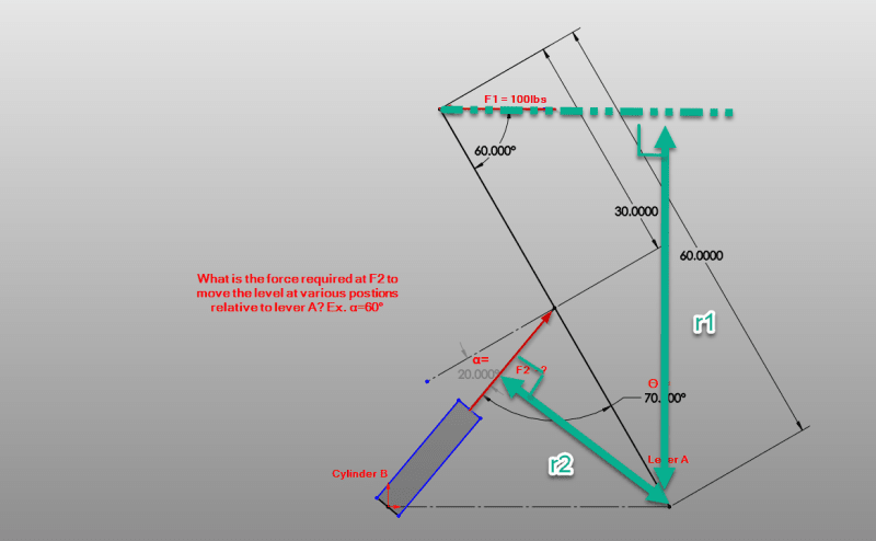
Both of these forces have two components projected onto the lever arm coordinate system. One of the components is parallel with the lever, the other component is perpendicular to the lever. Only the perpendicular forces need to be included when summing the moments about the hinge (the other components are inline with the lever and cause no moment).

If you write you the perpendicular components of force in terms of the respective angles, you can setup a system of equations and solve.

For example,the perp. component of F2... F2perp = F2 cos (alpha). F1perp = F1 sin (60).

Not clear if the angle for F1 stays constant or if the force is supposed to stay horizontal. Lets just call the 60 deg, beta. Then F1perp = F1 sin (beta).
If you do it this way then r1 and r2 become constant.

Some geometry is needed to solve the angles in terms of each other. In fact I think you would need to have the offset of the hinge at the base of cylinder B to properly express this. If the angles arent changing it become easier.

You can simply sum the moment about the hinge and only include the perp. components. 0 = F2perp*30 - F1 perp*60 ....> F2perp = F1 perp*60/30 ...> F2 = F1 perp*2/cos(alpha) ...? F2 = 2*(F1 sin(60))/cos(20) = 184.3 #.

If you can solve the relationship between alpha and beta, then you can write them up as an equation and solve the same equilibrium equations parametrically and prepare a graph of F2 vs alpha.


I can't help but get the feeling that this is a classroom assignment. It certainly looks and reads like one.

John R. Baker, P.E. (ret)
Irvine, CA
Siemens PLM:
UG/NX Museum:

The secret of life is not finding someone to live with
It's finding someone you can't live without
 
Yea I guess it does look like an assignment. Hopefully I didn't give away the cake. Looking at it again, you can solve the geometry because you know that the hinge of cylinder B is at the same height as the hinger of lever a.

okay OP its your job to make the graph and show us that you can do it by yourself.
 
Doesn't look like a textbook. Looks like stock SolidWorks with a touch of markup.

The problem looks like a run-of-the-mill actuator problem. Could be anyone anywhere.
 
T[sub]1[/sub] = T[sub]2[/sub]
F[sub]1[/sub]r[sub]1[/sub] = F[sub]2[/sub]r[sub]2[/sub]

"r" is the perpendicular distance to the force vector--simple trig

Lever_Arm_Force_markup_rhclrh.png
 
Is the lower point of "lever A" pinned to the ground (or just sitting there) ?
Id the upper point of "cylinder B" pinned to "lever A" or would is slide along the lever as it pivots ?

Lever A is a three force member.

Does the result depend on the spring curve of "cylinder B" ?

I'm sure this is a text book question.

"Hoffen wir mal, dass alles gut geht !"
General Paulus, Nov 1942, outside Stalingrad after the launch of Operation Uranus.
 
Hey guys, sorry for the late response. Definitely not a textbook question. I have a parallel linkage mechanism I'm working towards developing and I wanted to simplify the linkage to get the force on one arm/side. See attached spreadsheet and linkage images with complete geometry. F1 does indeed stay "horizontal/constant direction".

I'm not the greatest with calculations like these. If I can calculate the force on one side/arm, I can size the actuator, pins, and structure correctly and accurately.

Thanks for any help on this.
 
 https://files.engineering.com/getfile.aspx?folder=0b5c404a-6860-459b-acef-fc6d97a7c42c&file=Lever_Arm_Force_Calculations.png
Is the base of the actuator B a fixed distance from and at the same elevation as the hinge of lever A? I believe you need this info to solve the geometry.
 
in your s/sht, "2" is a nasty way to express the lever arm lengths.

you determined "alpha2" from CAD ? (for different "alpha1")

I wonder if it'll work as imagined ... if cylinder B is a hydraulic cylinder, won't the load/deflection be a function of cylinder's stiffness curve ?
I imagine that at some starting position the load is applied and the position of lever A will change until the compression of the cylinder creates the force required.

"Hoffen wir mal, dass alles gut geht !"
General Paulus, Nov 1942, outside Stalingrad after the launch of Operation Uranus.
 
"Is the base of the actuator B a fixed distance from and at the same elevation as the hinge of lever A? I believe you need this info to solve the geometry."
No, but wouldn't the forces acting on the lever arm from the load and the cylinder be calculated from the angles?

The spreadsheet is an approximation of angles from min/max to get a force range.
 
What kind of help do you need? Its apparent from your diagram that you understand something about the functions of force vectors their components. Have you had the training on how to calculate the resulting variables? If not, that is beyond the scope of a question on a forum page.

If so, are you just wanting someone to calculate this for you and then just give you the answers? Are you wanting to know the forces and moments at various points of lever rotation? Are you wanting a spreadsheet that will spit out some answer given certain inputs? Are you wanting to know max and min values? Or have you actually done the work and you need someone to validate or confirm your results?

Your diagram is nice, but your question is very vague.
 
I am looking for some help in setting up the calculation to find the force required by the actuator to move the lever with the applied force. Driftlimiter and tick gave some helpful insight into how i might go about calculating with various angles/arm lengths. Essentially i need to size an actuator, but i need to determine the highest load first.

I can set up a spreadsheet, but I'm not sure my math in the above spreadsheet is correct, although the results seem to make sense.

 
the maximum load on the actuator is only one of the sizing dimensions. You also have to consider the actuator stiffness, the response curve.

How critical is this "parallel linkage" ? Will people get hurt if it fails ??

Tick's "r1" and "r2" are a good guide to the mechanical advantage (disadvantage ?), moment arms about the pivot point (of lever A).

"Hoffen wir mal, dass alles gut geht !"
General Paulus, Nov 1942, outside Stalingrad after the launch of Operation Uranus.
 
Status
Not open for further replies.
Back
Top