Continue to Site

Eng-Tips is the largest engineering community on the Internet

Intelligent Work Forums for Engineering Professionals

  • Congratulations SSS148 on being selected by the Eng-Tips community for having the most helpful posts in the forums last week. Way to Go!

LFRS - Podium Construction Wood on Concrete - Masonry Shafts 4

Status
Not open for further replies.

RFreund

Structural
Aug 14, 2010
1,885
I'm curious to hear opinions on which would be a better choice for the LFRS for 4 floors of wood construction on top of concrete podium. Either using many wood shear walls (interior and exterior) or if the layout lends itself to it, using the Masonry walls of the elevator/stair shafts?

I'm wondering if shrinkage would be an issue if using the masonry shaft, however you could use vertically slotted holes I suppose. Any advantages to one or the other?

EIT
 
Replies continue below

Recommended for you

I vote wood.

1) Unless your diaphragms are very rigid, that will be the real load path regardless of your choice.
2) It will reduce diaphragm demands.
3) You get better seismic force reduction factors compared to ordinary shear wall systems.
4) Less demand on drag strut connections to shear walls. Those are tricky with CMU.
5) Vertical slots don't work reliably. Often, designers will introduce a wood bearing wall around the shaft to address shrinkage rather than connect to it. Vibration is another reason to do this.

I like to debate structural engineering theory -- a lot. If I challenge you on something, know that I'm doing so because I respect your opinion enough to either change it or adopt it.
 
I vote wood also. Koot did a good job summarizing why. It's worth mentioning that if your shear walls are 2x4 walls, the spacing of them is probably going to be dictated by boundary element capacity. I'd also avoid any shear walls where they may be plumbing lines, even if mechanical chases are frequent. I would also try to keep sheathing limited to one side of the shear walls. If possible, get wood walls around your shafts to help with shrinkage; the slotted holes don't perform very well and we've had contractors actually install one end low in anticipation for shrinkage. It worked fairly well actually, but we warned them ahead of time and the contractor was very experienced with multilevel wood construction.
 
Thanks for the suggestions.

To play devil's advocate here:

1. If you utilize the masonry walls then you don't have much concern for the interior walls and coordinating all the plumbing locations.
2. You have a fewer areas of higher level detailing; could be tricky anchoring the wood walls to the concrete/precast podium floor slabs.
3. If you don't utilize the masonry walls, you still must deal with them. You would want to avoid putting shear into them and also still need to account for shrinkage, so you have detailing here anyway.

Questions:

Kootk said:
Often, designers will introduce a wood bearing wall around the shaft to address shrinkage rather than connect to it.
Is the masonry wall then a stand alone shaft? Or if not, how is it braced at each level? I suppose this is how you deal with my point 3 above. Is there another way to detail this area?

Kootk said:
Vibration is another reason to do this.
Not sure what you mean here?

Mike20793 said:
It's worth mentioning that if your shear walls are 2x4 walls, the spacing of them is probably going to be dictated by boundary element capacity
You mean the spacing between shear wall lines, right?

Thanks for the replies!


EIT
 
I'm sure if you do the calculations, you will get that the wood diaphragm can be assumed as rigid, especially in the direction of the corridor (if there is a central corridor). The problem is the getting the load through the wood diaphragm into the masonry shear walls. Every plan offset causes force concentrations in the diaphragm that cannot be resisted by the sheathing (by code) so you're going to have straps and blocking at any plan offset and I can't even imagine getting collectors to work (depending on the actual plan size). I've done several cold-formed stud buildings on concrete podiums in the past year where we used the shafts to resist lateral forces and even with composite slabs, it was difficult to get the collectors and drag struts to work out and wind controlled. When there are frequent shear walls (and better yet, if there's a corridor), the flexible diaphragm assumption radically simplifies the detailing. When the corridor is present, offset shear walls that are not full depth of the diaphragm will cause a force couple that can be taken out by shear walls in the corridor.

The bracing of the shafts can be complicated, especially at elevator shafts. We often design them as standalone shafts, or justify some kind of portal frame action where we had large openings. They see very little load in the end, so it's usually not that difficult. What will hurt your head is when you think about the clashing of the shaft and wood building at the top floors.

I was referring to the spacing between shear wall lines. For typical four story wood buildings, I often use PSL posts in 2x4 shear walls just to handle the compression from overturning. Sheathing is usally 7/16" on one side with 4 or 6 inch edge nailing. Shear walls with 2x6 studs have little or no problems, typically.

Also, don't forget about wood diaphragm aspect ratio limitations. In most cases, my plan dimensions wouldn't allow for only the shafts to be used. Let us know what you go with; I have also thought about using the shafts on a job, but my boss quickly dismissed it.

 
I more or less agree with most of your satanic advocacy RFreund. To further promote the interests of goodness and light...

RF said:
If you utilize the masonry walls then you don't have much concern for the interior walls and coordinating all the plumbing locations.

Your demising wall will still likely be very important, heavily loaded bearing walls. It's not as though you'll be just turning a blind eye either way.

RF said:
You have a fewer areas of higher level detailing; could be tricky anchoring the wood walls to the concrete/precast podium floor slabs.

Firstly, I don't find that the higher level detailing required for the use of interior shear walls is all that bad. The walls are usually long and uninterrupted so things are manageable. I like it a whole lot better on a CIP podium than I do on precast however.

My second point is a bit frou-frou but I'll throw it out here anyhow. I don't feel that connection complexity varies linearly with load (C ><> L). Rather, I feel that it varies with some exponent of the load such as 1.5 or 2.0 (C ><> L ^ 1.5). This favors distributing load resistance throughout the building in my opinion. I feel that it will yield a more efficient solution, both in terms of construction cost and design effort. Distributing load resistance throughout a building also improves redundancy which is nice although not required in most instances.

RF said:
Is the masonry wall then a stand alone shaft? Or if not, how is it braced at each level? I suppose this is how you deal with my point 3 above. Is there another way to detail this area

Yes, yes, and almost certainly.

RF said:
Not sure what you mean here?

I have clients that have expressed concern over elevator vibrations telegraphing their way into the neighboring tenant spaces. I'm not sure how much truth there is to that. This obviously favors isolation.

Mike said:
I'm sure if you do the calculations, you will get that the wood diaphragm can be assumed as rigid

In my opinion, much depends on the details used at the partition walls. In my area, the sheathing won't be continuous. Instead, we'll transfer shear across with connector hardware. And, either way, the state of the union regarding chords in these kinds of buildings is sketchy at best. These issues, and others, make me quite skeptical of treating wood diaphragms as rigid. This, as you implied, is particularly the case in the transverse direction. I take comfort in the fact that, with a strong corridor wall and two strong demising walls, each unit could probably act as a stand alone three sided building if it had to. In fact, I suspect that may actually be the more realistic load path (three sided with some nominal capacity at the exterior).

I like to debate structural engineering theory -- a lot. If I challenge you on something, know that I'm doing so because I respect your opinion enough to either change it or adopt it.
 
Why not use both? The more walls you use the smaller the demands are all around. Lighter nailing, fewer holddowns, etc.
 
Koot,

I've heard about the discontinuous sheathing before, but I've never seen it. What is the purpose of it? Is it just to reduce noise transfer across units? Like you, I only use the the rigid diaphragm assumption when I have no other choice, ie shear walls in the corridor only. Otherwise, I find the flexible diaphragm detailing fairly easy, even with a significant amount of plan offsets. The point you make about redundancy is great. That is one thing all these wood buildings have in common.
 
@Mike: yup, noise is the thing. There are STC details that can compensate but our builders don't like the cost of them. I bloody hate it, truth be told.

So when you do rigid diaphragm and corridor walls only in the longitudinal direction, that means that you're discounting the exterior walls altogether right? I think that I agree with that, I just want to confirm that's the approach that you're proposing.

I like to debate structural engineering theory -- a lot. If I challenge you on something, know that I'm doing so because I respect your opinion enough to either change it or adopt it.
 
The way things have been going with architects, there's little to no exterior walls to use that meet the aspect ratio requirements, or the walls are very difficult to get the load into them since this is where the plan offsets usually occur. I very rarely get wood buildings that have straight exterior walls. The 2015 SDPWS has updated the rigid diaphragm section specifically addressing shear walls in the corridor only. They also changed the maximum cantilever diaphragm length from 25 ft to 35 ft. I always met the 35 ft requirement but rarely met the 25 ft requirement, so this is a bonus. Using the new provisions hasn't been an issue yet for jobs that are still under the 2012 IBC.

Basically, I use flexible diaphragms perpendicular to the corridor. If the demising/party walls are offset, I will try to take the force couple out in the corridor. If they are offset too much, I just provide full depth blocking and a strap or a shear truss. I've found (and confirmed by talking to Terry Malone) that it is often better to just provide full depth collectors than try to detail transfer diaphragms. When I'm looking parallel to the corridor, I almost always use rigid diaphragms and make nearly every corridor wall a shear wall. This is because I use sheathing on the corridor side of the wall (to avoid MPE lines punching through my sheathing) and architects will have to fur out the remaining walls to match the shear walls anyways. I almost never use the gyp board to resist shear because of the penalty on the seismic forces. The fact that the exterior walls are sheathed the same as shear walls in the same loading direction, even though they aren't true "shear walls" is just belt and suspenders, in my opinion.

For loading parallel to the corridor, I will provide shear trusses and straps or blocking and straps that align with and lap the most "interior" exterior wall and span between my shear walls perpendicular to the corridor. This basically makes my flexible diaphragms transfer diaphragms when load is applied parallel to the corridor. I've also used them as chords for loading perpendicular to the corridor, but only if the plan offset is small, ie less than 6 or 7 feet. This helps mitigate the discontinuous chord forces that often dictate transfer diaphragms. We've debated the effectiveness of these chord members when they are interior of the edge of the diaphragm and I think that it is still very much up for debate, but it seems to work okay for now.
 
Mike said:
I have also thought about using the shafts on a job, but my boss quickly dismissed it.
My situation is actually the other way around. I've been trying to increase our efforts to making sure we have complete load paths and details for it. Ever since reading Malone's book a couple years ago I've been trying to get us more inline with the spirit of his book. We do a bit of plan review and I've tried to push it on to others as well.

@Kootk -> good points

Has anyone actually provided a separate gravity framing plan and lateral framing plan as suggested by Malone?

Kootk said:
In my area, the sheathing won't be continuous. Instead, we'll transfer shear across with connector hardware.
Not to get too far off topic, but does this mean that the sheathing stops at the ceiling or... not sure what discontinuous sheathing looks like.

Mike said:
For loading parallel to the corridor, I will provide shear trusses and straps or blocking and straps that align with and lap the most "interior" exterior wall and span between my shear walls perpendicular to the corridor.
I can't seem to follow this last paragraph although it seems that there is some good information there I just can't picture it, could I bother you for a sketch or another shot at explaining what is going on there?

So it seems that things get dicey either way (using masonry or not). I mean if you have a stand along shaft then you still have differential shrinkage so you may actually build the wood walls around it shorter. However, you also are looking at a pretty sizable gap (wood shear wall deflection + diaphragm deflection) if you don't want the masonry walls banging into the wood walls at the upper floors. If you have precast at the podium there could be a difficult connection at the podium level. I suppose you would grout the hollow core plank solid and use a post installed anchor or if you had to some sort of through bolt with plate.
If you try to transfer shear, you are looking at some sort of vertically slotted connection which no one seems to be thrilled with. Or maybe you put some heavy elastomeric bearing pads on each side of the masonry wall and bolt them to some super heavy drag struts [ponder]. You masonry wall will be heavily loaded and get ready for some big foundations. I do like the idea of redundancy but I suppose you will get that to some degree even with only relying on the masonry.
I'm not sure if there is enough evidence one way or another? Unless your diaphragm ratios don't work, which may be an issue in the transverse direction as you likely won't have a continuous chord unless you put in a bunch of strap and blocking between exterior wall offsets. Even then it may not be deep enough...


EIT
 
For loading perpendicular to the corridor I use flexible diaphragms; when the load is parallel to the corridor, I typically use a rigid diaphragm. When load is perpendicular to the corridor, the plan offsets cause discontinuous chord forces. I will place shear trusses with straps or straps and blocking at the most "interior" exterior wall to act as the chords for the flexible diaphragms. This is the subject I said was still up for debate as I'm not totally convinced on their effectiveness when the plan offset is large. When load is parallel to the corridor, these shear trusses or straps and blocking act as collectors to deliver load from the plan offsets. Since they are in a continuous line within each flexible diaphragm, the flexible diaphragm becomes a sort of transfer diaphragm for the rigid diaphragm. Does that make more sense? I tried coming up with a sketch, but there was just too much information to try and fit. To answer your earlier question, we have recently started doing lateral and gravity plans because the plan callouts for straps and blocking can quickly clutter up a plan.
 
@mike - thanks it is making more sense. A couple of follow up questions:

Let's call the rectangular diaphragm bounded by the most interior, exterior walls and/or the truss/blocking between them, the main diaphragm. So your plan offsets create areas of the diaphragm that our outside of the main diaphragm. When looking at forces parallel to the corridor walls - Do you consider the offset portions a cantilever diaphragm where you transfer shear at the previously mentioned trusses/blocking and develop the chord forces into the main diaphragm?

EIT
 
@RFreund - I do not consider them cantilevered if they are 6 feet or less, and I generally will only use this approach if the plan offsets are minimal, say 1 or 2 plan offsets per flexible diaphragm. I will sometimes add an additional shear wall perpendicular to the corridor to limit the number of plan offsets in a given flexible diaphragm. The value of 6 ft. comes from the updated cantilever diaphragm provisions in the 2015 SDPWS. In my opinion, it's easier to add another shear wall than it is trying to detail a cantilever diaphragm off a main diaphragm. We have had issues with multiple member collectors and how they line up during construction, specifically trusses that share a 2x4 load bearing wall.
 
RFreund said:
Has anyone actually provided a separate gravity framing plan and lateral framing plan as suggested by Malone?

I haven't. I'd love to get a look at one though.

RFreund said:
does this mean that the sheathing stops at the ceiling or... not sure what discontinuous sheathing looks like.

I was referring to the floor sheathing rather than the shear wall sheathing RFreund. Basically, the air gap between demising walls is also a gap in the floor plywood/OSB. Don't judge me; I'm a slave to my market.

@Mike: thanks for taking the time to post your last comment on July 22nd. It was enormously valuable to me. And, to be honest, I only understood about half of what your wrote. That's not because you explained it poorly. Rather, it's because the issues are pretty complex. I'm pretty desperate to understand the parts that flew over my head though. I'm going to whip up some sketches over the next couple of days that show my interpretation of your comments. If you're able to spare the time, please comment on my sketches to steer me in the right direction.

I like to debate structural engineering theory -- a lot. If I challenge you on something, know that I'm doing so because I respect your opinion enough to either change it or adopt it.
 
For the perpendicular to the corridor condition I tend to use every party wall and any bearing walls interior to a unit as shearwalls. There are so many walls in that direction that the penalty on gyp board for seismic doesn't matter much. I don't worry too much about the chords as those forces stay quite reasonable if you use every wall you can find. It also helps lessen the amount of holddowns. I will sometimes even look as the diaphragm as rigid in the perpendicular to the corridor condition. Using all the walls keeps the chord forces small and helps with that dang torsional wind case ASCE7 requires. I will also use the block because it is there and the building is going to know it is there unless you isolate it so why not use it.
 
@Koot - That last paragraph I wrote came out horribly. It's difficult to explain without sketches and when I sketched something up, it was so cluttered it became even more confusing. Feel free to send over some sketches for comment.

@dcarr - I've thought about doing as you mentioned. My last big wood job, the architects actually complained about the number of shear walls. My shear wall spacing was actually dictated by boundary element capacity for most shear walls. I looked at using the gyp board to save on sheathing without changing the shear wall spacing. I was able to use gyp board on the upper floors, sometimes upper 2 floors, but on the bottom floor, some of my shear walls required sheathing on both sides; the idea was almost a wash on the quantity of sheathing. Since they were already complaining about the number of shear walls, I didn't want to add more, so we just stuck with using sheathing only. We have been seeing architects isolate the shafts more and more.
 
Query #1

mike20793 said:
Basically, I use flexible diaphragms perpendicular to the corridor. If the demising/party walls are offset, I will try to take the force couple out in the corridor.

Is it like the sketch shown below? If so:

1) Is that inconsistent with the flexible diaphragm assumtion in the transverse direction?

2) How do you actually, rationally transfer the moment from the party wall couple to the corridor couple? It's all fine and good to have a rigid diaphragm but the loads still have to make their way around some how.

Capture_d2t5g9.png


I like to debate structural engineering theory -- a lot. If I challenge you on something, know that I'm doing so because I respect your opinion enough to either change it or adopt it.
 
Query #2

mike20793 said:
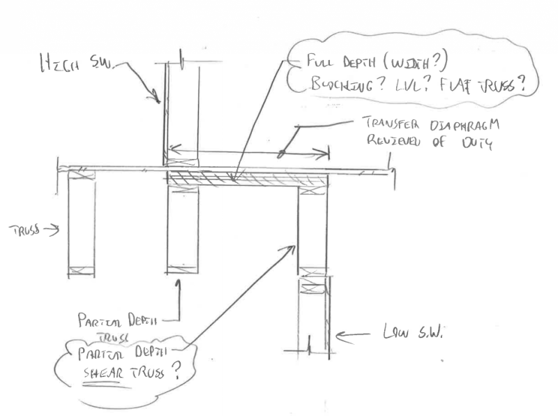
If they are offset too much, I just provide full depth blocking and a strap or a shear truss. I've found (and confirmed by talking to Terry Malone) that it is often better to just provide full depth collectors than try to detail transfer diaphragms.

This is the bit that I'm most curious about. If you and Terry have figured out a kick-ass new innovation, I want to know about it darn it! Do you mean full width collectors as I've shown below? It looks a little crazy, particularly for larger wall offsets. But then, I can't see any other way around having your floor sheathing function as a horizontal transfer diaphragm.

I just noticed that I'm failing to show the double walls at my party walls. They complicate matters so I'm just not going to bother.

Capture_dpkqz9.png


I like to debate structural engineering theory -- a lot. If I challenge you on something, know that I'm doing so because I respect your opinion enough to either change it or adopt it.
 
mike20793 said:
For loading parallel to the corridor, I will provide shear trusses and straps or blocking and straps that align with and lap the most "interior" exterior wall and span between my shear walls perpendicular to the corridor. This basically makes my flexible diaphragms transfer diaphragms when load is applied parallel to the corridor.

How is it that the flexible diaphragms are transfer diaphragms for load parallel to corridor? They sound more like cantilevered diaphragms to me.

mike20793 said:
We've debated the effectiveness of these chord members when they are interior of the edge of the diaphragm and I think that it is still very much up for debate, but it seems to work okay for now.

I'm very much in support of this concept. I do it all the time for steel buildings where the exterior framing will step all over creation in plan but, right behind that, there'll be a nice straight run of axially connected girders. You may find an unproven, related theory of mine interesting...

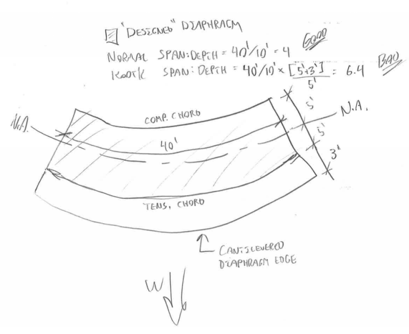
I believe that the purpose of diaphragm span to depth ratios may be to limit the amount of inter-panel axial strain developed between the sheathing panels that we assume do not participate in resisting flexural tension and compression stresses. Consequently, I've been calculating a modified span to depth ratio for diaphragms that have overhanging sheathing beyond the chord members as shown in the sketch below. I think that, calculated this way, the axial strain in the sheathing should be equivalent between diaphragms with and without overhangs. I compare these values to the code limits and assume that they're okay if that checks out. And yes, this is pure KootK fiction -- no code basis to speak of.

Capture_npgmr7.png


I like to debate structural engineering theory -- a lot. If I challenge you on something, know that I'm doing so because I respect your opinion enough to either change it or adopt it.
 
Status
Not open for further replies.

Part and Inventory Search

Sponsor