Continue to Site

Eng-Tips is the largest engineering community on the Internet

Intelligent Work Forums for Engineering Professionals

  • Congratulations SSS148 on being selected by the Eng-Tips community for having the most helpful posts in the forums last week. Way to Go!

LFRS - Podium Construction Wood on Concrete - Masonry Shafts 4

Status
Not open for further replies.

RFreund

Structural
Aug 14, 2010
1,885
I'm curious to hear opinions on which would be a better choice for the LFRS for 4 floors of wood construction on top of concrete podium. Either using many wood shear walls (interior and exterior) or if the layout lends itself to it, using the Masonry walls of the elevator/stair shafts?

I'm wondering if shrinkage would be an issue if using the masonry shaft, however you could use vertically slotted holes I suppose. Any advantages to one or the other?

EIT
 
Replies continue below

Recommended for you

mike207093 said:
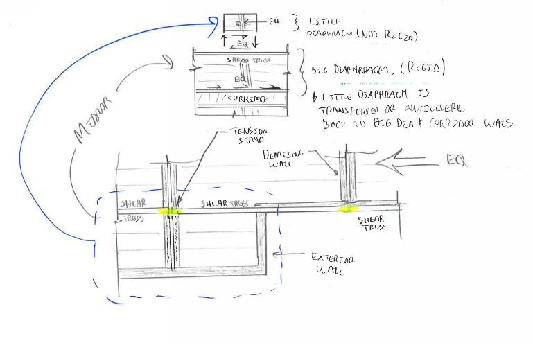
. When load is parallel to the corridor, these shear trusses or straps and blocking act as collectors to deliver load from the plan offsets. Since they are in a continuous line within each flexible diaphragm, the flexible diaphragm becomes a sort of transfer diaphragm for the rigid diaphragm.

RFreund said:
Let's call the rectangular diaphragm bounded by the most interior, exterior walls and/or the truss/blocking between them, the main diaphragm. So your plan offsets create areas of the diaphragm that our outside of the main diaphragm. When looking at forces parallel to the corridor walls - Do you consider the offset portions a cantilever diaphragm where you transfer shear at the previously mentioned trusses/blocking and develop the chord forces into the main diaphragm?

You're both talking about the phenomenon shown below where the chunk of diaphragm beyond the chord proper "rides along" with the main, rigid diaphragm, right? FWIW: I have no idea why I didn't draw my inset detail the same way up as the main plan. I'm too lazy to fix it unfortunately.

Capture_f6zodz.png


I like to debate structural engineering theory -- a lot. If I challenge you on something, know that I'm doing so because I respect your opinion enough to either change it or adopt it.
 
Some additional Comments:

I was actually thinking your Query 1,2 and 4 were all the same. I had interpreted the "offset" to mean walls on the same floor being offset from eachother.

If they are offset too much, I just provide full depth blocking and a strap or a shear truss. I've found (and confirmed by talking to Terry Malone) that it is often better to just provide full depth collectors than try to detail transfer diaphragms.

I took this to mean that the collector extends across the depth of the diaphragm. I assume Mike means it is difficult to detail a transfer diaphragm because your collector must extend between chords, which means you would need a chord at the end of your collector. Although I'm still a bit fuzzy how the cantilever influences the main diaphragm design if it falls between perpendicular shear walls... I think I'm just adding to the confusion...

[link Diaphragm with Cantilever][/url]

Side question: has anyone used embedded images with Onedrive, if so, how?

EIT
 
Koot,

Response to Query #1:
It's so difficult to explain without sketches, so I apologize if I was unclear. I was referring to horizontal offsets within the same plan rather than horizontal offsets between levels. I will avoid these vertical offsets at all costs, but I have done them before. You're diaphragm below takes a concentrated load from the shear wall above and a distributed load from the lateral loading at that level. I don't think it's possible to detail without having a transfer diaphragm at the level below; at least that is how I've done it. With plan horizontal offsets, you are basically tying the two offset walls together with a "lapped" collector. This only works because the corridor is detailed to be a full depth shear wall/collector and can handle the rotational force through it's shear panels for loading parallel to the corridor. See the attached example to see what I'm talking about. Hopefully it will become more clear and maybe clear up Query #2.
 
 http://files.engineering.com/getfile.aspx?folder=a4f47a4c-011e-4596-9efc-ea0e72febf96&file=plan_offset_shear_walls.pdf
KootK said:
How is it that the flexible diaphragms are transfer diaphragms for load parallel to corridor? They sound more like cantilevered diaphragms to me.

You are right, each flexible diaphragm is basically an open front structure for loading parallel to the corridor.

I'm glad you agree with the chord members being interior of the exterior walls. We use a similar reduced depth to span ratio, but it hasn't controlled on any multilevel wood buildings yet.
 
RFreund said:
I took this to mean that the collector extends across the depth of the diaphragm. I assume Mike means it is difficult to detail a transfer diaphragm because your collector must extend between chords, which means you would need a chord at the end of your collector.

Yes, exactly. By the time you provide the additional chords and the blocking and strap to transfer the force, you're better off just providing full depth blocking and straps or a shear truss and strap. It results in less blocking and less straps overall. This is why I asked Terry about it. I like the idea of having transfer diaphragms, but they can be unnecessary when the diaphragm dimensions are relatively small. I posted a numerical example above showing the lapped shear walls in lieu of full depth blocking.
 
Mike,

What is the architect's complaint about more shear walls? The walls already exist as bearing walls sheathed with 5/8" gyp each side. Is the complaint the extra nailing/screws?


On a different note, has anyone ever heard of a diaphragm failing in one of these multi-family type podium slab apartment buildings due to the lack of a chord?
 
@dcarr - Honestly, the architect had no clue what they were doing on that job. They saw more shear walls and immediately equated it to more labor, holddowns, sheathing, etc when in actuality, there wasn't any real difference and there might have even been a cost savings. As a firm, we prefer to have the least amount of shear walls as possible because when they are 2x4 walls, the studs get butchered by subcontractors. From a design standpoint, I agree with you; the drywall is there regardless and a few extra nails/screws isn't that labor intensive. On that project, they had some crazy 12 - 20 ft parapets on parts of the building, so gyp board wasn't useful in those locations. I'm going to push harder for your approach in the future.

Yes, I have seen a diaphragm "failure" before. I quoted failure because the sheathing usually just pops up and the carpet or tile gets slightly distorted; I haven't seen anything worse than that. I've seen panels split before, but there were probably other forces at work. It's an easy fix and because the panels are relatively small and it's usually just a few in an area that get damaged.
 
@Mike:

I've got it now. Thanks for the clarifications. It had never actually occurred to me to lap splice offset party walls across the corridor. It makes perfect sense though. I was feeling pretty sorry for you when I thought that your architects were making you stagger all you shear walls 6-7' from floor to floor.

One last question for you: what area of north america do you work in? Your work sounds head and tails above anything that's being done withing 500 miles of me. I might have to move to where you're at so that I can play in the lateral wood sandbox too.

I like to debate structural engineering theory -- a lot. If I challenge you on something, know that I'm doing so because I respect your opinion enough to either change it or adopt it.
 
Interesting. Seismic, high wind, or just a butchered design? I tend to wave my hands and magically say the lack of a true chord is ok given all the other pieces working as the unofficial chord. I only do this when I can keep the chord forces low however.
 
@dcarr - The few I've seen have been older buildings (built in the late 70's or early 80's) that we investigated, so I'm sure it was a combination of poor detailing and poor design and maybe poor construction (the panels were never glued to the framing). Typically, the "failure" occurs at reentrant corners that had popped the sheathing. I keep quoting failure because it doesn't look like a failure compared to concrete or steel. Most people wouldn't even recognize it other than the lump in the carpet.

@Koot - I had one job like that earlier this year where the architect absolutely refused to align a loadbearing shear wall and it danced from floor to floor. We basically had to walk the contractor through what we were doing on each floor and he still messed it up several times during construction. That would have been a great case for gravity framing and lateral framing separate since the plan detailing was so intensive. In the future, I will avoid that again at all costs. I work in the southeast US. We have been seeing a huge increase in the number of these type of buildings (all on PT podium slabs). In general, I found the first one to be very difficult and it was probably my most difficult wood building to date. After that, it became a lot easier and a lot faster; you quickly learn how to save yourself some work, even when the plan isn't regular and the demising walls don't line up.

A few things I'v picked up on for multistory wood buildings:
-Generally (not always), 2x4 walls are controlled by stud capacity, 2x6 walls are controlled by crushing of the sill plate when the plate and stud strengths are the same.
-2x4 shear walls can often require engineered lumber posts to get the boundary elements to work in compression.
-Shear transfer from level to level in the corridor can be tricky when the corridor side of the wall is sheathed.
-Avoid placing shear walls near potential plumbing lines, even when there are mechanical chases present. Have a field fix ready either way because the subcontractors will likely mess up the sheathing and/or studs.
-Make sure your shafts and wood framing play well together for shrinkage. We've actually had a couple jobs recently that had wood stair shafts. Framing these out while keeping the fire rating can be difficult.
-Support brick off each floor with engineered lumber rim boards if there is brick all the way up the exterior. Use a lipped brick if the architect will allow it.
-Make sure the architect is aware of potential shrinkage early on. I usually just send them an output from the Simpson shrinkage calculator.
-Watch fire separation walls, the diaphragm is discontinuous across them.

 
Just thought I'd share that I got a building earlier this week that has extreme vertical discontinuities on the bottom wood level (the one supported by the podium slab). It's extremely difficult to drag the cumulative shear force into vertically offset shear walls, so I looked at using the shafts for lateral. The building was approximately 120 ft wide by 80 ft deep in the direction of wind loading. They have some large parapets at the top of the roof and just on that level, there was 32 kips of force going into one shaft wall. The diaphragm demand required a blocked diaphragm (which may be fine), but we could not find any way to effectively drag the force into the walls. The maximum collector force was about 20 kips. It took a beefy member to handle the compression case of the collector, but anchoring it to the wall for the tension case may be impossible with wood members. I used a semirigid diaphragm analysis.
 
Offtopic a bit - How do you guys justify fire ratings in multi-story timber buildings? Over size primary members? Everything is concrete here [ponder]

And what sorts of timber do you usually specify? Plenty of banter about 'shrinkage' so I assume unseasoned? softwood? Thanks everyone. [bluegreedy]
 
Great thread, guys. I agree with Mike's assumptions regarding flexible one way and rigid the other. I have come to the same conclusion.


When I am working on a problem, I never think about beauty but when I have finished, if the solution is not beautiful, I know it is wrong.

-R. Buckminster Fuller
 
BowlingDanish said:
Offtopic a bit - How do you guys justify fire ratings in multi-story timber buildings? Over size primary members? Everything is concrete here [ponder]

Our building code (IBC) is actually pretty cut and dry about the fire ratings of wood buildings. There are plenty of approved assemblies for up to 2 hour ratings (Type III construction). Most wood buildings atop concrete podium slabs in my design area are rated as Type V construction, which has the least stringent fire rating requirements. Most of the fire resistance comes from the covering of the wood, but the depth and breadth of a member do add to it because of the char rate of the wood (the NDS has a dedicated chapter for it). It is common to have poured gypcrete in the units and lightweight concrete in the corridors to achieve the required fire rating. Gypsum wallboard, insulation, membrane, etc add to the fire resistance rating.

BowlingDanish said:
And what sorts of timber do you usually specify? Plenty of banter about 'shrinkage' so I assume unseasoned? softwood? Thanks everyone.

Mostly softwoods and engineered lumber made of softwoods. I typically usd southern pine, douglas fir, and spruce-pine-fir. I use PSL, LSL, and LVL for engineered lumber products. The engineered lumber will be kiln dried because of the manufacturing process. In my area, solid sawn lumber will be seasoned to a moisture content of under 19%.
 
Mike said:
I used a semirigid diaphragm analysis.
[ol 1]
[li]Very nice. How did you do this? More specifically how did you model the wood diaphragm?[/li]
[li]Are you thinking of the vertical slotted connection detail at the masonry shaft? I think we are going with the masonry walls as well but they are still working through some things and we may need to use the interior walls.[/li]
[/ol]

Another request we have received is that for some higher end condos, the developer/arch does not want demising walls to be shear walls (nor bearing walls) because people are buying multiple units or even whole floors and wanting to knock down all the walls.

Thanks again for all your input.

EIT
 
I used RISA 3D and modeled the diaphragm as plane stress plate elements. I'm hesitant about the slotted connections at the shafts; they just don't perform well in wood. I've used two alternatives: have the contractor install the end of the joist framing into the shaft low so it shrinks to level (close to it) or use engineered lumber plates in areas 'close' to the shafts. Having the contractor install the end of the joist low has worked okay, but the better option is using the engineered lumber plates and reducing the span of the members framing into the shafts. Your going to have some differential shrinkage issues, but if the contractor knows about it ahead of time, he can mitigate it.
 
Status
Not open for further replies.

Part and Inventory Search

Sponsor