Eng-Tips is the largest engineering community on the Internet

Intelligent Work Forums for Engineering Professionals

  • Congratulations waross on being selected by the Tek-Tips community for having the most helpful posts in the forums last week. Way to Go!

Lift Pit - Eccentricity Piles

Status
Not open for further replies.

drago8

Civil/Environmental
Jun 26, 2015
41
0
0
BN
Dear All,

How to do the analysis of lift pit with eccentricity in the piles? Do I treat it as flat slab?

Actually, the situation is like this. Due to the site condition, the contractor had to adjust the piles which in turn creates eccentricity in the piles. They are no longer at the sides. Now, I want to analyse the effect of these piles to the slab of the lift pit.

Thanks for your help.

#LoveWins
 
Replies continue below

Recommended for you

How are the soils for laterally supporting the pit?
What is the allowable out-of-vertical tolerance for the lift mechanism?
 
Drago8 said:
Do I treat it as flat slab?

Yes. Slab/pile cap. The side walls will make it more rigid than your run of the mill slab.

I like to debate structural engineering theory -- a lot. If I challenge you on something, know that I'm doing so because I respect your opinion enough to either change it or adopt it.
 
SlideRuleEra,

Attached is the drawing for the as-built piling and proposed. Green = designed location, Purple = as-built location.
The thickness for the slab is 500mm THK.

Buggar,

The soil is a bit weak. The pile penetration is roughly 37m DEEP.

KootK,
Ah noted on that, will check using that concept. You are saying the side walls will help the eccentricity issue?

Appreciate all for your response.

#LoveWins
 
 http://files.engineering.com/getfile.aspx?folder=7b96da1f-9b70-46fd-a8fc-54f885e77d9b&file=piling_layout.pdf
Meh. If this is just moderate gravity load, you should be fine. If it's a shear wall shaft, that pile at the bottom left might give you some trouble.

I like to debate structural engineering theory -- a lot. If I challenge you on something, know that I'm doing so because I respect your opinion enough to either change it or adopt it.
 
I would treat the entire pit with walls as a rigid pile cap for determining load distribution to each pile. Then:
- Check max pile capacity
- Check that reinforcement is developed at the pile in both directions.
- Check 1 way and 2 way shears (not going to be an issue with a well anchored wall), have a look at CRSI
 
drago8 - Since we don't know (geotechnical) pile capacity compared to (structural) pile load I can't just glance at the drawing and say things are fine. What I can say is there are at least three separate issues to address:

One issue involves the four perimeter pile. The pit walls "stiffen" the structure. Since the piles remain more or less directly under the walls the "strength" of the foundation is not really a concern... for those four piles.

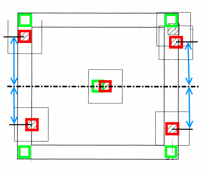
The second issue is geometry of the as-built pile locations. Fortunately all four perimeter piles are dislocated in the same direction and roughly the same distance compared to both principal foundation centerline axes. Each of the four piles will share load (approximately) as intended in the original design. Check to see if the (geotech) allowable pile capacity was conservatively specified. If so, should be ok. The marked up sketch below highlights the relative displacement graphically for one axis. The center pile is not displaced a significant distance.

The third issue concerns the center pile and is perhaps the most important. I asked about slab thickness for a reason. Think of a pile as an upside-down column and the slab as the column's footing. Punching shear has to be considered. A slab that is 500 mm thick is not much of a pile cap. If the "square" on the drawing around the pile represents a build down, that will help. Check for punching shear, if it is a problem take appropriate action as a field change.

Enlarge the slab so that it completely covers the top of the as-built piles. The new edge of the slab should extend at least 75 mm beyond the edge of a pile so that the entire pile top is bearing on reinforced slab, not on the 75 mm (or so) of slab concrete rebar cover. Of course, the pit wall remain where they need to be.

BTW, the original design is NOT "pile-driver friendly". Design pile locations are way too close to design slab edges. There needs to be enough clearance so that a driven pile can be misplaced by a reasonable distance in any direction (often 75 mm) without having to make field changes to slab dimensions.

Plan_Scan-1_a2djko.png


[idea]
[r2d2]
 
What type of piles are they? They look like square columns on square footings.

Why are there two very close together in the upper right hand corner?

BA
 
Status
Not open for further replies.
Back
Top