Continue to Site

Eng-Tips is the largest engineering community on the Internet

Intelligent Work Forums for Engineering Professionals

  • Congratulations KootK on being selected by the Eng-Tips community for having the most helpful posts in the forums last week. Way to Go!

Lifting Chain Idler Pulley Design

Status
Not open for further replies.

mattyjb88

Mechanical
Sep 15, 2010
12
Hi all
I am completing a design check for a lifting chain idler pulley. The client is wanting to move to a stainless steel chain which is of slightly different dimensions to the original chain. I am struggling to find design guidelines for the design of this type of pulley. I gather this arrangement puts the links into some level of bending so guess there is a guideline/rule-of-thumb around the pulley diameter to link pitch ratio.

Note this is a lifting chain, not a roller chain or leaf chain. Perhaps now an unusual application, however this is a 1940's era design.

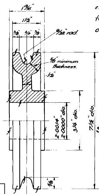
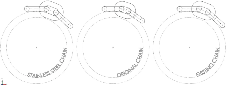
Images of the parts as follows:
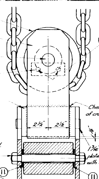
GA_qacl7f.png
Pulley_okrzwx.png


Keen to hear peoples thoughts / experiences on this.

Thanks
 
Replies continue below

Recommended for you

The chain only contacts the outer diameter of the pulley, so groove shape is unimportant. You could fabricate the pulley from three discs clamped or welded together.
 
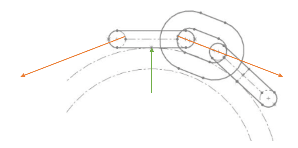
Yes I agree the chain only contacts the OD - so long as the groove is deep enough. However you will see in the sketch below that the links which wrap around the OD are subject to minor bending in addition to tension. I would have thought there would be a strength reduction factor, or a minimum diameter to be applied?
Chain_Sketch_p2ipjm.png
 
The Westinghouse code formula would give you the minimum diameter for the link bar stock assuming only bending stress. It accounts for fatigue.

Add the tensile stress from the load. Then you should have a good idea of what a given chain can handle. Might be good to make a Mohr's circle for the situation.

I am not an expert in stress analysis. This is an interesting problem, simple but serious. Where are the experts?

Since there is fatigue in this arrangement, a static load test would not be good enough, but I would load that rig up until something broke.

 
I don't know why I didn't think of this before. Mark's Mechanical Engineering Handbook and Machinery's Handbook have good information on this subject.

Why not consult with manufacturers of this equipment? Here is just one result from a search:


I think you can get an answer to your question without a lot of work.
 
Load sheaves appear to be designed to not put any bending forces on the links. So it seems rather a non-issue.
 
I disagree. The links in plane with the pulley are in pure tension as you say, however those perpendicular which sit on the pulley OD are placed in bending as per the FBD below:

Chain_Forces_i7oad6.png


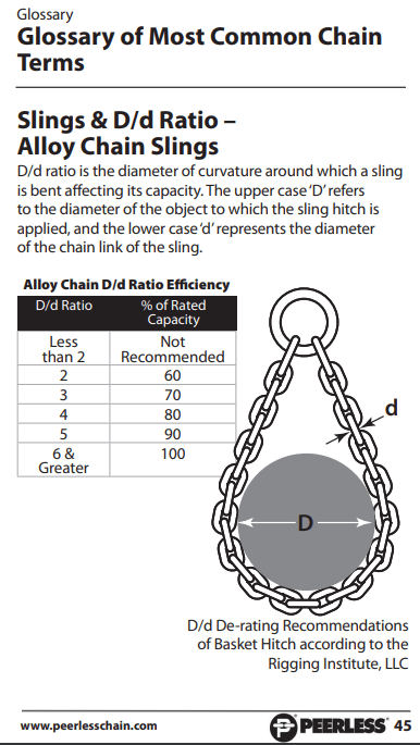
Some guidance on allowable is given below, which in this case the client is satisfied with (we have lots of margin on WLL), however this is for alloy chain so strictly speaking shouldn't be applied to SS chain. Also it doesn't provide any of the theory behind it.

Chain_Ratio_Extract_ovhgtq.png
 
My point was that if you look at pictures of actual load sheaves those links lie on flats, not curved surfaces.
 
I happened to find this standard, maybe it has a reference to pulley design. Might be worth the $42 in this case:

ANSI/ASME B29.24-2002
Roller Load Chains For Overhead Hoists
This Standard covers specialized roller chains that are designed specifically as load chains for use in overhead hoists.

 
Status
Not open for further replies.

Part and Inventory Search

Sponsor