Eng-Tips is the largest engineering community on the Internet

Intelligent Work Forums for Engineering Professionals

Lifting solution for large steel structure

Status
Not open for further replies.

majkus

Mechanical
Dec 7, 2018
5
0
0
PL
Hello,

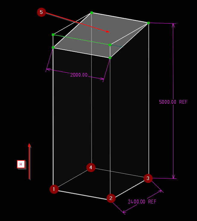
I am looking for lifting solution , I have a steel structure of weight - 2,6 tonne that needs to be lifted by H = 650mm with MANUAL actuation , if needed cordless drill is applicable as well.
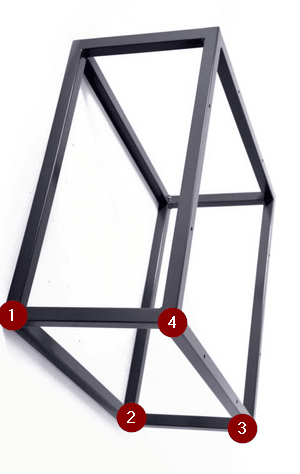
Picture below ( dimensions in mm )
H_rodts5.png

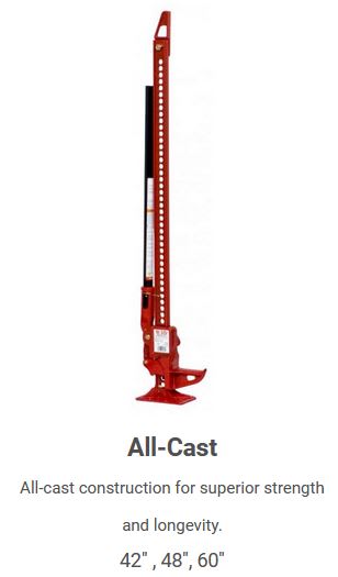
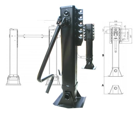
For now i have thought of landing gear jacks in each corner [1,2,3,4] however i couldn't find suitable stroke, 510mm is maximum.
2_kwukdz.jpg


After lifting of H , 2 people will be working on the top - surface ( 5 ). Surface 5 is inclined about 10 degrees horizontally. Assume that CoG is perfectly in between support 1,2,3,4 at 2000mm height.


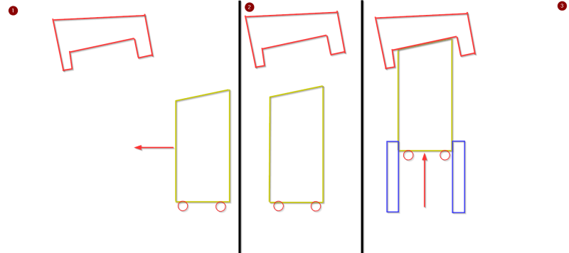
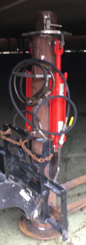
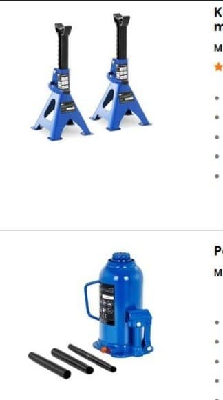
I also thought of something central with retractable jack stands with some sort of ratchet ( green ) and central lifting with hydraulic piston (red) with a hand pump
See video below :
1_oyuczb.jpg

What other solutions or comments come to your mind?
 
Replies continue below

Recommended for you

this looks like homework ?

what does "Assume that CoG is perfectly in between support 1,2,3,4 at 2000mm height." mean ?

Will two people seriously be working on an inclined surface 5m above the ground, with no fall protection ?

If you think 4 bottle jacks work (how will you co-ordinate them together ?) then lift 1/2 way, support structure on pads, reposition bottle jacks and repeat.
How will the bottle jacks grab hold of the sides ??

another day in paradise, or is paradise one day closer ?
 
Assume that weight distrubution is equal on 4 corners, and don't worry about the people above the ground, they are protected , it is out of the scope of my question.
I assume that 2 people simultaneously operate to lift the whole structure, i could add visual scale / spirit level or something that could make their actuation kind of synchronized.
The idea is to connect jacks in pairs, previously with landing gears 2 jacks were connected with a shaft as can be seen on image above.
Lift has to be continuous, can't split it into lift some stroke -> stop -> support -> reposition -> lift again . I assume bottle jacks could work if they were connected to a 1 hand pump with hydraulic hoses ?
 
majkus said:
Assume that weight distribution is equal on 4 corners
That assumption is not and never will be valid with what you are considering.

majkus said:
don't worry about the people above the ground, they are protected
As responsible professionals we are concerned. Your proposed solution has many potential failure modes that put the people at risk.

 
since you're "arbitrarily" constraining things (why one continuous lift ?), build your own bottle lift.

Again, is this a real problem, or is it homework ?
If it is a real problem, there are many things you are blissfully ignoring, that could easily get people hurt.

Of course, you can reasonably say "I'm part of a team, and my task is to lift this thing. Other people will take care of other issues."

If you do use bottle jacks,
1) how will you co-ordinate them (maybe 4 people with tape measures talking to each other) ?
2) how will the bottle jack interface with your structure ?

another day in paradise, or is paradise one day closer ?
 
majkus,

Have you talked to the people who will be lifting it? You need to know what tools they have, and what their skill set is. They may have safety concerns you did not think of.

--
JHG
 
I appreciate your concern but there are parts of the design i am not willing to describe, share for obvious reasons. Yes IT will be built for real. Of course i can agree on not equal load distribution in real life scenario, this structure is modeled already and cog is very near to the theoretical cog i described above but i have given you this so you know that from theoretical static point of view load distribution is equally divided by 4.

Continuous lift is a client constrain, explained that lifting adds much complexity.

I already explained how i wanted to actuate, with 2 people and 2 Jacks connected with shaft . Jacks were screwed to be fixed with the structure .I dont know about bottle Jack, that's why i asked what could be the idea for synchronizaton movements ( 1hand pump connected to 2 bottle Jacks?)
 
ok, the issue with the bottle jacks you can buy is not enough travel. Maybe you can get a set for 650mm travel by special order, maybe you'll have to build your own. There's only 0.65 tonne per jack, so a typical car jack would do the job.

I don't understand why the client is telling you "one continuous lift" and not two lifts with a repositioning stage in between ... it's not like the 2 stage lift would take significantly more time, if that's their concern.

If you plan the build, and place lifting fittings under the corners, it'd make the lift easier.

another day in paradise, or is paradise one day closer ?
 
The problem with most of these continuous lifts is maintaining stability. Most jacks aren't suitable for managing stability and depend on other restraints. They also depend on being directly beneath the item being lifted, but I see no provision for that. So, for this abstract problem the abstract jacks will abstractly fall over.

This requirement is within the capacity of a pair of pallet lifts. Example: Technically any manually pumped mechanism, including hydraulic, depends on stopping and automatically bracing, so it not continuous.

I don't recommend people working on a 10 degree sloped steel surface. Slipping and falling nearly 6 meters will injure them.
 
With a lot of work, hooking up 4 double ended hydraulic actuators in series might get you there. The initial filling of the chambers would be tough. There's also fluid compressibility, leakage and unequal cylinder areas that would mess you up.

Have you considered non-back drivable screw drives? Put a pulley on each screw and drive them from the same motor and belt.
 
I don't see a center of gravity on the sketch ...

I do not believe: "Assume that CoG is perfectly in between support 1,2,3,4 at 2000mm height."

A more accurate CG would be very simple to calculate ...

Like most third-world postings, you only get a little bit of information at a time and important details are "assumed" away

What happens if one jack slips and the structure is suddenly supported on only three points ?

Why would you not lift this structure like you would lift a house?

.....Make a slight lift using posts, install two new lifting beams, attach the lifting beams to the bottle jacks, then complete the lift

MJCronin
Sr. Process Engineer
 
Majkus:
You say…, “there are parts of the design i am not willing to describe, share for obvious reasons.” O.K., but, nobody is asking for your bank account number or the keys to your house, or national security info. And although, apparently not obvious to you, there are “obvious reasons” why you will never get a meaningful discussion of your problem if you won’t give enough meaningful engineering design info so that we can start to understand what you are really trying to do, and what the structure looks and acts like, other than a half-assed, no sizes and dimensions, no connections, unbraced stick figure. What does any lifting device fit into or around, or attach to? We really can’t see it from here, and we can’t read your mind either. How do you fit a 26” long lifting mechanism in a zero volume leg, or around an undefined leg shape? Can this lifting operation be done by one, two or four people? Must it be done at nodes 1, 2, 3 & 4, the base? Or, might it be better if done by the workers up on the platform, at the four corners, so that only the top 3 or 4’, the platform, is moving up and down? Does a continuous lift mean perfect motion like a CNC machine motion, or might it mean 6” increments, 5 minutes to reposition the four jacks, and then another 6” lift? The platform legs lock into 6” ratchet steps to allow moving the jacks, no need to build a new cribbing system at each step, pretty darn continuous, and practical, and economical.
 
if it hasn't been built yet, erect a 650mm high platform under it.

How will the structure be held in place ?

another day in paradise, or is paradise one day closer ?
 
Yeah, I agree with rb1957 suggestion of a platform during the fabrication of the steel structure, then I would explore the use of a lattice or hydraulic crane to lift it. A spreader bar system would be needed so as not to crush the top of the steel platform which could happen if you only use lifting cables connected to the crane hook.
 
Ok additional information :
1 ) structure to be positioned under the red fixed element
2 ) structure aligned ready to be lifted
3 ) structure lifted to align with red fixed element with blue elements
d_a7qcum.png


It is preferred to have manual actuation for 2 people. As you can see above we have to be somewhat aligned to the red surface, but not lift it ! We don't want to get involved with pressure or amperage adjustment to secure it, we think of visual inspection with mechanism like semaphore, railway signal that when it hits the surface it rotates to show that we are aligned.
BhfEpfenhofen_Ausfahrsignale_Talaufwaerts_II_ztm36w.jpg

It would be great if it could be integrated in platform, not as external lifting device such as fork lift truck. I assume that at nodes 1,2,3 and 4 we need supports , maybe fixed ones to provide stability after lifting, however it doesn't necessarily mean that the lifting should be in 4 corners, i don't know this, so i am asking your opinion.
We have a frame box structure with steel profiles 100x100x5.
dd_vlka7g.png
 
If a forklift is not possible, I might consider pipe within a pipe type supports, crossbraced for stability, both with holes for pins at various elevations, using bottle jacks or hydraulic cylinders to lift the inner pipes.
Post_Jack_bpwqyx.jpg


Could these people make you custom jacks?

Or these guys:
 
The venerable Hi-Lift jack, where every 'notch' lifted is the same lift to synchronize your manual team's effort. Rated for 4.6K lbs or 2.1 kg. More lift than you need but a controlled lift "on the count".
hi-lift_jack_zjl46j.jpg
 
I would like to look at this from a different point of view. 650mm is not a lot of lift and what I'm about to propose might seem like a lot of effort for such a small lift, but it might be worth it. The main problem that I see with hoisting it from the bottom is that it might be hard to see when the two structures make contact. You could end up crushing the one structure into the other one by 10mm and your guys operating the jacks won't even notice. Hydraulic and even mechanical jacks can be quite strong. What I propose is the following: Build two towers of scaffolding, one on either side of the structure. Then you can have one guy on each tower. You attach a chain block to the red structure and then hoist the blue structure up towards it. The guys operating the chainblocks will have direct line of site of when the two structures make contact. You might even be able to use the scaffolding to aid with attaching the two structures to each other (I'm assuming you are attaching them to each other). You don't have to worry about jacks slipping or sliding or failing and in my experience chainblocks are reasonably reliable. I'm not entirely sure what kind of space you've got but maybe this can give you some food for thought.
 
Status
Not open for further replies.
Back
Top