Continue to Site

Eng-Tips is the largest engineering community on the Internet

Intelligent Work Forums for Engineering Professionals

  • Congratulations GregLocock on being selected by the Eng-Tips community for having the most helpful posts in the forums last week. Way to Go!

Light Gauge Arches 2

Status
Not open for further replies.

WARose

Structural
Mar 17, 2011
5,594
I'm somebody who has designed some light gauge/cold formed steel in my time......however, its always been straight. In observing a lot of construction over the years, I have seen situations where they used (cold formed) arches as part of the framing. This weekend I walked into a building with (load bearing) light gauge studs in progress and looked at how they did it. Attached is what I observed.

One thing I left out of my pic was the attachment of the arch ends to the the studs: just a couple of screws (flange to flange).

This left me with a few questions for anyone with experience in light gauge:

#1: What sort of calcs are necessary with this? My guess is: there are no "arch" calculations at all on the bent member (because the header is made very stiff).....and it's just a (out-of-plane) bending C-section. That brings up another problem:

#2: Any curved beams calcs for the "arch"? With the stud set up....you'd think there would be (due to out-of-plane loads).

Thanks.

 
 https://files.engineering.com/getfile.aspx?folder=78d30594-80e0-4977-a834-b0f6b9f71984&file=light.gauge.arch.pdf
Replies continue below

Recommended for you

1) My thoughts below and, mostly, as you expect.

2) CFM design is cowboy country. I've seen crazy stuff, even from engineers working on behalf of the major suppliers.

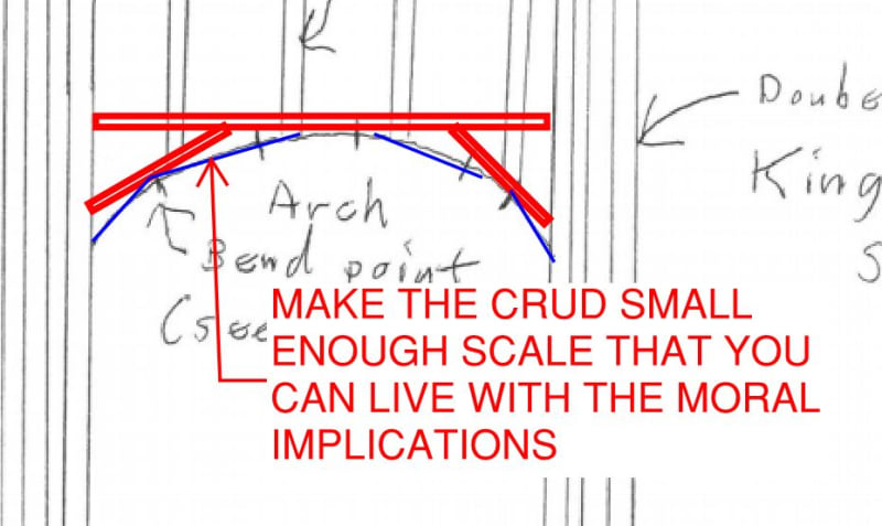
3) The flange splice detail makes me question the competence of the designer for what you saw. I feel that splicing would be ineffective and wasteful.

C01_nx5puv.jpg
 
Just the guy I hoped would comment (because I know you've done a lot of light-gauge stuff).

With your detail.....doesn't that still leave some wind load out there for the arch to handle out of plane? That unnerves me to a degree.

 
My thought is the header is too stiff to allow any load passing to the structures below. The arch trim may be hanging by the studs that essentially were designed as hangers.
 
WARose said:
With your detail.....doesn't that still leave some wind load out there for the arch to handle out of plane? That unnerves me to a degree.

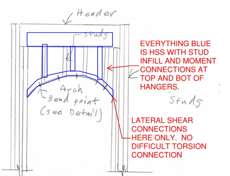
Yup & me too. The name of the game is keeping the cringe worthy bit as small a scale as possible. For things of a larger scale than you've sketched, I might:

1) Header things off with "real" framing more inticately;

2) Start thinking about rolled HSS frames for the truly large scale. The expense will raise eyebrows. Sometimes this is the only reasonable approach if your arch is large and holding up brick. In some loose homage to a proper arch, these things often support brick veneer of some strife.

At some point you just throw in the towel and go HSS everything.

c02_xkvroc.jpg


C04_yv09og.jpg
 
Cowboy country for sure. Depending on where the ceiling is with respect to the arch, I have done propped cantilever studs off a light gage girt just above the ceiling line. This requires a connection of the backspan to the roof or floor beam. The girt is placed behind the common studs but strapped to the kings.
 
“The moral implications” of the fake arch - haha I love it. I have a few of them around the place where I’ve oversimplified something to make my life east and the carcass pads it out to make it look way more impressive than it actually is! Only engineers know..
 
We have a designer in our office that does pretty much only light gauge. With the designs that come in, they have to get extremely creative. I've seen them use XR's intent a lot. Anytime there's a light gauge ceiling, you'd better bet they're likely using it to brace some funky bulkhead or wall detail.
 
I used to do Light Gage about 50% time. Now only about once per year when I am the EOR. It def. makes you dig deep into your creativity toolbox. For that, I am a better Engineer,
Happy to be away from that specialty, however. I really disliked the race to the bottom, the incompetence of the EOR's and their unwillingness to own their mistakes and try to make things right.
 
About 30 years ago I did a light gage design for the arches over entrances for a new Dillard's department store. They were all the same look, but the structure could be whatever the designer wanted. I did the design using short segments of light gage on the arch and then covered it all with plywood to get the smooth appearance to receive the EIFS covering.

Since arches are inherently strong, you can also notch the flanges of a track to create the arch and rivet or weld the folds in the flanges. You'll be surprised at the strength, even though you can't easily analyze the result.

 
Since arches are inherently strong, you can also notch the flanges of a track to create the arch and rivet or weld the folds in the flanges. You'll be surprised at the strength, even though you can't easily analyze the result.

I don't wonder at all about the in-plane ability of the arch (as shown) because in-plane, it really doesn't see anything because of the stiffness of the header. It's the out-of-plane strength I wonder about. That's a (horizontally) curved beam....and for a light gauge member ....it does't take much to blow them out.

I might do some calcs later on this week (based on what I saw) and see what it could take.
 
Out-of-Plane, don't you think the complete assembly (studs + metal arch + face coverings) has any rigidity? It could be small, but just the panel needs to sustain the wind. Obviously it will not stand for hurricane, neither the posts/frame.
 
[blue](Sandman21)[/blue]
Simpson has a product called Ready-Arch framing.

Thanks for that info Sandman. I contacted them and they said that the Ready-Arch does "not have any load ratings and would be used for interior, non-load bearing applications".

[blue](retired13) [/blue]
Out-of-Plane, don't you think the complete assembly (studs + metal arch + face coverings) has any rigidity? It could be small, but just the panel needs to sustain the wind. Obviously it will not stand for hurricane, neither the posts/frame.

Yeah, that's definitely one possibility....but that plywood gets pretty flexible in that situation. I'd think the curved beam stiffness could/might take over first. (Something else for me to look at when I get a chance.)
 
Not just the possibility, the metal arch has very limited stiffness as the flanges been cut to form the shape. You will need to design the studs and the facial panel as built-up member, with the panels taking up most of the bending stress. And, the studs shall be so placed to prevent buckling of the arch trim.

Also, upon completion, isn't the panel be rigidly supported on 3 sides?

The flanges may have been cut....but see the splice detail. And again: I doubt very seriously the [presumably] plywood panel (with 3 side support) would have the stiffness to prevent a great deal of force from going to the arch and (likely) wrecking it. (At least as per what i posted originally.)

When time permits, I'm going to run 2 scenarios: the original (and see what happens first).....and then with it modified as per Kootk's pic (on 6 Jul 20 21:20) and see if that little bit of wind load wrecks it.

But paying customers come first. [smile]
 
Status
Not open for further replies.

Part and Inventory Search

Sponsor