Continue to Site

Eng-Tips is the largest engineering community on the Internet

Intelligent Work Forums for Engineering Professionals

  • Congratulations GregLocock on being selected by the Eng-Tips community for having the most helpful posts in the forums last week. Way to Go!

line bore of multiple plates

Status
Not open for further replies.

Minnyman

Marine/Ocean
Jul 28, 2012
11
hello all,

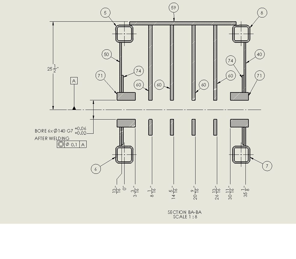
My question is about boring out a hole through 6 plates spaced 3" apart. The plates are 1" thick with the the two end plates 6" thick. On the old drawing I am updating they have a diameter dimension with a g7 tolerance. The diameter dim says to BORE 6X DIA5.0 G7 +0.xx/-0.xx and on the other side of the part is a concentricity call out on the end hole with the datum as the axis of all the holes. The drawing view is a section view to the middle of the holes. (dang after re-reading this even I'm confused now, I'll create a jpg of the view tomorrow at work). Well if anyone can understand this let me know.

My question is this: is there a correct or better way to dimension these holes? They are for a pin that will be inserted through the plates. The pin will support sheaves on a crane. I was thinking that you would have to show concentricity to each hole on the plates and not just the end one.

Thanks a bunch,
Minnyman
 
Replies continue below

Recommended for you

What drawing system are you using, as this may impact things.

Sounds problematic if ASME is invoked then datums on center lines isn't correct.

Posting guidelines faq731-376 (probably not aimed specifically at you)
What is Engineering anyway: faq1088-1484
 
we use Solidworks 2013 and the ASME standard.
 
Check out ASME Y14.5-2009 Para. 7.5.3, especially Fig. 7-49 and 7-50
Still would be nice to see the sketch of your application.
 
LOL, OUR 14.5 IS FROM AROUND 1978.

AM STILL WORKING ON THE DRAWING VIEW JPG
 
Minnyman,

I strongly prefer it when holes are specified on each, individual drawing. In your case, if a pin must pass accurately through all the holes, it is impossible.

I would show that the holes must be located to some reasonable level of accuracy from a proper datum, and that they must be located with extreme accuracy to each other, thus showing that all must be drilled in one setup, after assembly.

You can use the top face and hole as datums to locate very accurately, the remaining holes. This would be the second block in your FCF. The 1978(6?) standard makes things interesting.

--
JHG
 
LINEBORE_zps13453f2f.jpg


here is the pic.

just a FYI I am not an engineer just a drafter. I have had some training with GDT but no where near as extensive as you guys.

the concentricity frame used to be on the right pointing to the first plate.

thanks
 
A couple of issues, I would say...
First: We don't know what datum A is. It shouldn't be tagged with an imaginary center line, because we can't touch a center line when we're making or inspecting the part, and also because it's ambiguous. There are many features that are shown on that center line and it's unclear which is the real feature to grab onto to establish the datum axis. The datum feature symbol should be tagged with a physical diameter, and then the real datum will be understood to be an axis still (but it will be taken from the diameter tagged with the datum triangle symbol).

Second, once the datum is ironed out, you'd be much better off with the position symbol than concentricity. You stated that you are just trying to align the holes so that a pin can be inserted through there. They might sound like they are doing the same thing, but the way they are defined is different enough to make a significant difference. Depending on the loads of the crane and strength / wall thickness issues, it's possible to also use an MMC modifier with position.

John-Paul Belanger
Certified Sr. GD&T Professional
Geometric Learning Systems
 
Since you are boring the holes in one setup, post-welding, I don't think that position is the easiest way to go. What you are really looking for is co-cylindricity, I think. The only geometric control that will achieve that is profile of a surface. You can use the size tolerance as indicated, and apply a profile of a surface control marked "6 HOLES". Alternatively, you can use a position control as J-P indicated, but without a datum reference, and then use the pattern of 6 holes to establish your primary datum axis.


Jim Sykes, P.Eng, GDTP-S
Profile Services TecEase, Inc.
 
Status
Not open for further replies.

Part and Inventory Search

Sponsor