hello all,
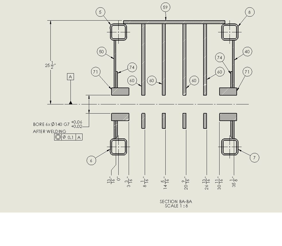
My question is about boring out a hole through 6 plates spaced 3" apart. The plates are 1" thick with the the two end plates 6" thick. On the old drawing I am updating they have a diameter dimension with a g7 tolerance. The diameter dim says to BORE 6X DIA5.0 G7 +0.xx/-0.xx and on the other side of the part is a concentricity call out on the end hole with the datum as the axis of all the holes. The drawing view is a section view to the middle of the holes. (dang after re-reading this even I'm confused now, I'll create a jpg of the view tomorrow at work). Well if anyone can understand this let me know.
My question is this: is there a correct or better way to dimension these holes? They are for a pin that will be inserted through the plates. The pin will support sheaves on a crane. I was thinking that you would have to show concentricity to each hole on the plates and not just the end one.
Thanks a bunch,
Minnyman

