Eng-Tips is the largest engineering community on the Internet

Intelligent Work Forums for Engineering Professionals

  • Congratulations waross on being selected by the Tek-Tips community for having the most helpful posts in the forums last week. Way to Go!

Line-Earth Voltage in 3Phase unbalance loads 6

Status
Not open for further replies.

MAZ13

Electrical
Apr 21, 2011
15
0
0
DE
Hi all,

If we have a 3phase unbalance load (400V L-L, 230V L-N nominal voltages), which all loads are on 1phase and the other phases are unloaded, is it expected that L-E voltage in unloaded phases changes? (anything rather than 230V?)

I know that by unbalance loading, neutral point displaces and neutral voltage is something rather than 0. Therefore I expect L-N voltage changes on all phases. But my question is about line to earth voltage.
I ask this question because software simulation of such unbalanced load by DIgSILENT power factory shows such strange results!
 
Replies continue below

Recommended for you

With an unbalanced load you will get a voltage drop on the loaded feeder conductor ans possibly the supply transformer. This may be significant.
With an unbalanced load you will also get a voltage drop on the neutral feeder. This may be significant. Additionally the neutral drop may have lessor ampacity than the line conductors.
Now, starting with an equal sided and equal angle star diagram and considering "A" phase to be the loaded phase,
The voltage drop on the neutral will be towards line "A" or "A" phase.
The voltage drop on the "A" phase feeder will be towards the neutral.
Now draw a triangle using the new position of "A".
The line to line angles are no longer 120 degrees.
Now using the new position of the neutral, draw a star diagram from the neutral to "A", "B", and "C".
The line to neutral angles are no longer displaced 120 degrees and while the voltage has dropped on "A"to neutra, you can see that it has raised slightly on "B"to neutral And "C" to neutral.
You don't want to add a grounded wye/delta transformer or a three phase motor to the mix.
It will get more interesting.

Bill
--------------------
"Why not the best?"
Jimmy Carter
 
Dear Mr. MAZ13
Q1. "...If we have a 3phase unbalance load (400V L-L, 230V L-N nominal voltages), which all loads are on 1phase and the other phases are unloaded, is it expected that L-E voltage in unloaded phases changes? (anything rather than 230V?). A. I am of the opinion that:
A1. with the N is solidly earthed:
A1.1, the loaded phase/line say A , V A-E will be lowered; due to the voltage drop in the transformer or the outgoing conductor,
A1.1 the loaded phase/line say A , V A-E will be


I know that by unbalance loading, neutral point displaces and neutral voltage is something rather than 0. Therefore I expect L-N voltage changes on all phases. But my question is about line to earth voltage.
 
che12345
Dear Mr. MAZ13
Q1. "...If we have a 3phase unbalance load (400V L-L, 230V L-N nominal voltages), which all loads are on 1phase and the other phases are unloaded, is it expected that L-E voltage in unloaded phases changes? (anything rather than 230V?)...".
A. I am of the opinion that:
A1. if the N is solidly earthed:
A1.1, the loaded phase/line say A , V (A-E) will be lowered; due to the voltage-drop in the transformer and the outgoing conductor,
A1.2 the unloaded phases/lines say B&C , V (B-E) and V (C-E) will [remain the same 230V irrespective of whether line A is loaded or unloaded],
Q2. "...I know that by unbalance loading, neutral point displaces and neutral voltage is something
A2. if the N is not earthed, when say A is loaded; the N is not at 0 (the earth reference),
A2.1 the voltage of the loaded line A V (A-E) and unloaded lines V (B-E) & V (C-E) will [not be] 230V, as N is not at O (the earth reference).
Che Kuan Yau (Singapore)
 
Dear Mr Che;
While your basic knowledge is very good, you obviously do not have a lot of North American experience.
You persist in assuming field conditions that don't exist in code compliant North American installations.
In North America the neutrals are earthed at the source.
Voltages measured at the load will be reduced by voltage drops in all current carrying conductors.
The neutral feeding a single phase line to neutral load will be one of the current carrying conductors and will experience a voltage drop.
It is a serious code violation in North America to ground a neutral at the load.
Even if there is an exception and the neutral is grounded at the load, there will be a voltage drop on the neutral path and this will be reflected as a voltage at the load that will be the source voltage minus the voltage drops on both the phase conductor and the voltage drop on the neutral current path.

If the neutral is not earthed, the phase to ground voltages will be indeterminate and subject to possible change when major branch feeders are connected.


Bill
--------------------
"Why not the best?"
Jimmy Carter
 
Dear All,
Q. "...If we have a 3phase unbalance load (400V L-L, 230V L-N nominal voltages), which all loads are ..."
A. With the voltage (400V L-L, 230V L-N nominal voltages ...) it indicates to be in the IEC world. Therefore, the US practice does NOT come into the picture.
Che Kuan Yau (Singapore)
 
I was not aware that IEC practice was to ground the neutral at each load. Thanks for the heads up.
Does that make this statement invalid?
Even if there is an exception and the neutral is grounded at the load, there will be a voltage drop on the neutral path and this will be reflected as a voltage at the load that will be the source voltage minus the voltage drops on both the phase conductor and the voltage drop on the neutral current path.

Bill
--------------------
"Why not the best?"
Jimmy Carter
 
Dear Mr. waross

1. Your learned advice dated 28 Sep 20 02:41 is out of the scope to the question asked.
2. "...I was not aware that IEC practice was to ground the neutral at each load..." .
No, it is NOT the IEC practice " to ground the neutral at each load..."
3. Your statement "...Even if there is an exception and the neutral is grounded at the load, there will be..." is irrelevant. Reason see above 2.
4. I will answer to (Mr. MAZ13) in greater detail on a [three-phase system with neutral but the neutral is isolated from earth], in a separate mail to follow.
che Kuan Yau (Singapore)
 
Let's say we have a 2500 kVA 3*400 V 6% short-circuit voltage grounded Y connected.
The copper losses 9000 W. Calculated Z=0.4^2/2.5*6%=3.8E-3 ohm[3.8mΩ]. In=2500/sqrt(3)/0.4=3.608E3 A [3.6084 kA]
R=9000/3/3608.4^2=2.3E-4 [0.23 mΩ]
X=SQRT(3.6084^2-0.23^2)=3.601 mΩ
A supply cable of 4*6 mm^2 copper XLPE insulated PVC jacketed of 100 m up to our main panel. x=0.144 ohm/km r=3 ohm/km Zcbl=sqrt(0.0144^2+0.3^2)=0.30035 ohm; Ycbl=Yo=1/0.30035=3.329
zcbl=0.3+j0.0144 ohm; Ycbl=3.326-j0.16 siemens
Let's say we have a single phase [phase R and N] 400/√3=231V loaded with 10 kW and cos(ϕ)=0.85.
Sload=10/.85=11.77 kVA; Iload=11.77/0.231=50.95 A [rated]
If the load is constant, we may calculate Zload=0.231^2/0.01177=4.5336 ohm YR=1/4.5336=0.220257 S
Actually ZRload=3.85+j2.388 ohm YR=0.1875-j0.1162 S[Siemens]
At main 3 phase terminals we have -almost-a unchangeable voltage of 400/sqrt(3)=231 V
Then we can neglect transformer impedance and cable impedance but we keep the neutral wire impedance in calculation.
From here we have a lot of way to continue calculation like Millman theorem, Kirchhoff and other. You may use absolute values or complex. Whatever the difference is less than 1%.
Using Millman theorem:
Vn[the voltage between the neutral at our main and the transformer neutral]
Vn= [VR*YR+VS*YS+VT*YT]/(YR+YS+YT+YLoad)
If YS=YT=0 then Vn=VR*YR/(YR+Yo)=14.35 V
Using complex numbers Vn=12.85-j6.63
Now Van=Va-Vn=231-14.35=216.65V
Using complex numbers Van=218.25V
Vbn=232 V
Vcn=243V
If we shall take Zo=∞ then Van=0.361431;Vbn=399.6;Vcn=399.8 V

 
Dear Mr. 7anoter4
1. Read the question carefully asked by Mr.MAZ13
Q. "... a 3phase unbalance load (400V L-L, 230V L-N nominal voltages), which all loads are on 1phase ..., is it expected that L-E voltage in unloaded phases changes? ... I know that by unbalance loading, neutral point displaces and neutral voltage is something rather and the than 0. Therefore ... But my question is about line to earth voltage...."

2. Mr. MAZ13 's question is " about line to earth voltage* "

3. Sorry, I am of the opinion that your learned advice is out of the scope, to the question* asked.
Che Kuan Yau (Singapore)
 
If we measure the voltage at the terminal of the randomly charged transformer, another added unbalance load does not produce a significant voltage imbalance..
What I understood it is about of local voltage to local neutral point grounded. I admit now that it is not clear from the o.p.
 
OP said:
I ask this question because software simulation of such unbalanced load by DIgSILENT power factory shows such strange results!
7anoter4 and I have been attempting to address this statement.
Another poster wishes to focus on a narrow interpretation of the question and dismiss any additional information.
7anoter4 and I are trying to address this comment (strange results) and explain the answer.
A simple answer is simply that the line to ground voltage will drop by the amount of voltage drop in the hot conductor.
A explanation of the "strange results" requires consideration of the voltage across the load, the voltage drop on the neutral conductor, the neutral displacement and the effect of the neutral displacement on the voltage to ground of the unloaded phases taken at the location of the unbalanced load.
Scope is where you find it!
Bill
--------------------
"Why not the best?"
Jimmy Carter
 
In USA the neutral is grounded only at the source. In IEC World in order to detect a leakage to ground the local neutral has not to be grounded locally. Exception: only in TT earthing system the equipment is grounded through equipment grounding locally.
 
Equipment grounding versus system grounding:
In the US equipment frames may be grounded locally to limit touch potentials.
System grounding refers to a connection between the system neutral and a ground source or electrode.
System grounding is done at only one location, at the source.

Bill
--------------------
"Why not the best?"
Jimmy Carter
 
LOL, there is no good answer without knowing the transformer and grounding configuration entered into the model.

How an installation is required to be wired in the NEC or the IEC worlds means jack squat when using a modelling program.
 
Thank you LionelHutz
However,I don't think you took my exercise seriously. Because o.p. threw an idea I tried to give it some clothes. Besides, I agree with what you said. Like the statement that it is very difficult to get on a plane while flying.
 
Hi all,

thank you for your answers. I think you got my question but your replies do not answer my question.

First to make assumptions more clear: neutral point at load is not earthed. It is abviously clear that by an earthed neutral on load star point we would have a voltage drop on phase A (loaded phase) and nothing more (no change in neutral or other phases voltages).

The question is about phase to earth voltage of unloaded phases, when neutral is not earthed at load terminals and load is just on phase A.

In this case, I expect that a voltage drop occurs on phase A (Va<230), voltage on neautral point raises (Vn>0), phase to neutral voltage on phase A reduce (Van<230) and phase to neutral voltage on unloaded phases increase (Vbn>230 and Vcn>230 because of displacement in neutral voltage point). But I don't expect any change in Vb and Vc! (should be: Vb=Vc=230) However, DIgSILENT shows change in Vb and Vc! and important point: this is because of cable. It means when I use a 3core cable, the results are so that I expect, but when I use 5 core cable, these strage results come out.

I have read your answers carefully. But I think when Bill talks about drawing a triangle, he assumes Vb and Vc are on the same place (as I am) and when 7anoter4 calculates Vbn and Vcn, he also assumes Vb and Vc are 230V.
 
From what I can understand, OP is asking a very teorethical question and che12345 is correct with his answer (but without any context, all the answers here are valid at some point):

MAZ13 said:
If we have a 3phase unbalance load (400V L-L, 230V L-N nominal voltages), which all loads are on 1phase and the other phases are unloaded, is it expected that L-E voltage in unloaded phases changes? (anything rather than 230V?)
I know that by unbalance loading, neutral point displaces and neutral voltage is something rather than 0. Therefore I expect L-N voltage changes on all phases. But my question is about line to earth voltage.

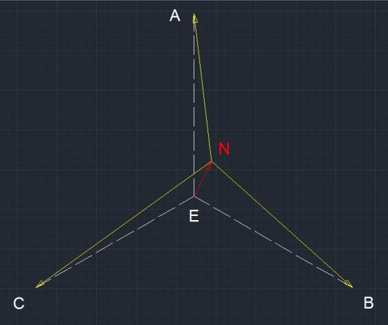
I think he is referring to the fact that in an ungrounded star system with an unbalanced 3 phase load, the neutral voltage (N in figure below) shifts from the theoretical earth potencial (E). This usually obtained with the symmetrical components method for solving unbalanced 3 phase systems.

neutral-shift_seguby.jpg


For the case mentioned by OP: all loads on 1 single phase, and the other 2 unloaded, there is no such phenomenon (in the symmetrical components kind of way) and the only neutral voltage displacement would be the one produced by the voltage drop on the neutral conductor as waross mentioned and 7anoter4 showed by example. This could be more or less noticeable depending on the neutral ground connection (far from the load-> more noticeable / close to the load -> less noticeable).

And to answer OP specific question: There will be no change of voltage on the unloaded phases with respect to earth E as che12345 already said, but it will with respect to neutral N as waross and 7anoter4 said.

Now, what is OP thinking or trying to simulate to bring up such questions?.. it beats me.

EDIT: Oops.. I was still typing when OP made the last reply and didn't read it untill I posted, but the core of my answer stands so I will not change it.
 
Status
Not open for further replies.
Back
Top