DrDrreeeaaa
Electrical
Hi All,
I need to source a 600A 5% line reactor for notching and harmonic mitigation of a 400V 550A three phase AC controller.
I am in Australia, and availability of such things is very difficult. 5% line reactors are not stocked at all, and 3% reactors are stocked but only in sizes below, say, 400V 300A. Anything else we generally ship them from the US at a 12 week lead time which our project can't tolerate.
Smaller reactors are available here in Australia and I was thinking maybe it's practicable to combine several smaller reactors to satisfy our requirements
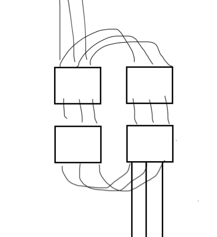
We would need 4-off total reactors, 2 in series, and then each group of 2 in parallel. Each reactor would be 320A 3% (0.075mH approx).
Is this totally crazy? Or is it simple, bread and butter? Obviously it seems simple when you do a calculation of parallel and series inductances, but I have never seen such a thing done practically.
Or are there even advantages to such an arrangement?
Or does anyone have an MTE RL-50013 lying around that I can buy off them!")
Appreciate anyone's thoughts.
I need to source a 600A 5% line reactor for notching and harmonic mitigation of a 400V 550A three phase AC controller.
I am in Australia, and availability of such things is very difficult. 5% line reactors are not stocked at all, and 3% reactors are stocked but only in sizes below, say, 400V 300A. Anything else we generally ship them from the US at a 12 week lead time which our project can't tolerate.
Smaller reactors are available here in Australia and I was thinking maybe it's practicable to combine several smaller reactors to satisfy our requirements
We would need 4-off total reactors, 2 in series, and then each group of 2 in parallel. Each reactor would be 320A 3% (0.075mH approx).
Is this totally crazy? Or is it simple, bread and butter? Obviously it seems simple when you do a calculation of parallel and series inductances, but I have never seen such a thing done practically.
Or are there even advantages to such an arrangement?
Or does anyone have an MTE RL-50013 lying around that I can buy off them!
Appreciate anyone's thoughts.