Eng-Tips is the largest engineering community on the Internet

Intelligent Work Forums for Engineering Professionals

  • Congratulations waross on being selected by the Eng-Tips community for having the most helpful posts in the forums last week. Way to Go!

Linear concrete stress-strain relationship: when is it valid

Status
Not open for further replies.

Greenalleycat

Structural
Jul 12, 2021
507
NZ
Howdy all,

I do my beam moment-capacity calculations from a typical spreadsheet that bases the capacity off a concrete strain of 0.003 and uses the stress block stuff - the same as you all do no doubt.
This is all fine and dandy until you run into a situation like mine, where you have steel with a low tensile strain capacity that is actually significantly more limiting than that concrete strain
To put numbers to it, my steel has an allowable strain of 1.5% - running a typical beam design check with concrete strain at 0.003 gives a steel strain of 4.5%, 3x the limit

So, I've built a new spreadsheet that allows me to set an upper strain limit on the steel then back calculates the concrete strain etc from there
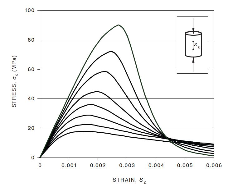
The problem is that I've had to make a fundamental assumption of a linear strain distribution through both the concrete and use this to calculate the concrete stress from stress = Young's Modulus * Strain relationship
I'm finding that I get concrete strains on the order of 0.001, or about 1/3 of the limit state strain, from this - is my assumption of linearity actually valid in this range?
 
Replies continue below

Recommended for you

GAC -
is your "allowable" strain a linear value? steel typically has a large non-linear strain region prior to failure.
and 1.5% strain is 0.015 in/in strain (unless I need more coffee), which is much higher than your concrete 0.003 in/in strain.
I thought concrete always cracked in tension before the steel rebar ruptured.
 
This all seems somewhat nebulous as the fraction of steel isn't mentioned, the location of the steel isn't mentioned, whether this is tensile or compressive isn't mentioned, and the steel alloy isn't mentioned.

The steel should have the same strain as the concrete it is embedded in, unless that isn't the use of the steel here.
 
The steel is a variety of cold-drawn mesh that was prevalent for use here but has seismic issues due to a fracture strain as low as 4%
Testing has shown that this mesh has effectively no yield plateau either so you do not get the non-linear region that is relied upon for ductility
There is a legitimate issue that this mesh can fracture entirely under seismic shaking which can lead to brittle and significant failures
The 1.5% is a Building Code value to be used in undertaking seismic assessments to reflect these concerns

The concrete strain of 0.003 (0.3%) is the ultimate concrete strain on the compression side, the steel strain of 0.015 (1.5%) is a tension strain
The assumption of a ULS reinforced concrete beam is that it has cracked so the concrete on the tension side is irrelevant at the critical section (as it has cracked so isn't contributing)

Dave - I don't think the particular parameters are significant here but if they are helpful, the example scenario is a 150mm thick panel of 40MPa concrete with 6.3mm mesh @ 150mm crs, Fy = 600MPa
Steel is discussed above
Strictly this steel is round bar mesh so it is likely to debond over the 150mm mesh pitch, but that assumption is a discussion for another thread
 
I see the problem - it seems like this is some standard analysis rather than a derivation of how the analysis should be done.

If that is the case then ask the Building Code authority what their analysis means.

If the concrete has cracked the distribution cannot be linear. Because there is steel reinforcement that also means the strain in the concrete cannot be linear if the reinforcement isn't on the neutral axis, which it won't be after the concrete cracks.

Past that, it sounds like a substandard steel unsuited for the application.
 
Yes the steel is substandard but such is the curse of living in a changing world, a huge amount exists in this country to undo the many (and ongoing) bad decisions that have been made
No choice now though as it is mandated to assess and upgrade the buildings around us, so here we are

The base problem is very simple, it's just a reinforced concrete wall panel
The complexity arises from the old steel being inadequate compared to modern standards, and hence failing critically when subject to modern design philosphies
An alternative analysis philosophy is required, which is what I have been deriving by flipping the calculation from being governed by concrete strain (modern philosophy) to governed by steel strain (required for this shitty steel)
The Building Code (or more accurately, the high-level seismic assessment guidelines) provide some critical parameters for this process but, as always, miss out the nitty gritty of how to execute this deviation from standard philosophy - hence me doing my own thing

The linear strain assumption is still valid across the cross-section, the same as in modern RC design
However, the deviation I need advice on is related to the stress-strain relationship within the concrete at sub-ULS loads as this affects the force equilibrium equations for calculating the wall's capacity
Normal philosophy simplifies the concrete to a rectangular stress block (the Whitney stress block) - but I do not know if this assumption is still the most appropriate model to use when we are at ~1/3 of the concrete's ultimate strain capacity

That is the portion I'm looking for engineering opinions on
 
Maybe look into how folks design concrete reinforced with FRP. That should help some.
 
This family of curves is from the commentary to the Australian concrete code.

It seems that your assumption of linear behavior up to 0.001 is generally fine except for lower strength concrete mixes.

Capture_gyugp7.jpg
 
Currently having a look at at 3.1.7 of Eurocode, assuming my PDF is the latest...direct equations for the stress/strain curve, option to use either parabolic or linear(that latter would be far simpler for section analysis

εc3 is min .175% from Table 3.1, so with the mesh failing at .15% your calculation stays in the linear zone on Figure 3.4

----------------------------------------------------------------------

Why yes, I do in fact have no idea what I'm talking about
 
Greenallycat, the analysis you are describing sounds a lot like the old Working Stress Method... cracked elastic analysis of reinforced concrete. An old boss of mine showed me it once, but I never used it in practice. It does have the assumption of linear strain across the section. You may be able to find literature on that method in older concrete or masonry texts?
 
I know this doesn't answer your specific question, but why not design the beam assuming a concrete strain of 0.003 and a maximum steel strain of 0.015? Based on linear strain compatibility and the steel strain being a maximum of 5 times the concrete strain, the distance from the steel to the neutral axis would have to be less than or equal to 5 times the distance from the neutral axis to the compression face. As long as that relationship is satisfied, the steel strain would not be exceeded.
 
If you want to use "unusual" stress-strain relationships for your steel and/or your concrete, my website ( has a downloadable spreadsheet that will analyse an arbitrarily-shaped cross-section whose steel and concrete follow completely arbitrary stress-strain curves (defined in piecewise-linear fashion).

[sub][ ]—————————————————————————————————[/sub]
[sup]Engineering mathematician/analyst.[ ] See my profile for more details.[/sup]
 
PMR06 said:
An old boss of mine showed me it once, but I never used it in practice. It does have the assumption of linear strain across the section. You may be able to find literature on that method in older concrete or masonry texts?

I find that a very strange comment.

Calculating steel and concrete stresses assuming linear behaviour for the steel and the concrete in compression remains an essential part of reinforced concrete design. If you don't do that, how do you calculate stresses or crack widths for crack control, or calculate deflections, or check stress ranges for fatigue checks when that is required?

For the analysis required in the OP, assuming linear concrete behaviour with a stress limit on the steel would be a conservative approach, or for something less conservative, the Eurocode linear-rectangular or parabolic-linear approach for the concrete, with a reduced maximum strain, would be reasonably straightforward to apply.

Finally, all standard design methods assume plane sections remain plane, and hence a linear strain distribution across the section, with the steel and reinforcement having equal strain. It's the stress that is non-linear.


Doug Jenkins
Interactive Design Services
 
Agreed, IDS. Perhaps my question was poorly worded but there seems to have been some confusion in the responses. The assumption of linear strain is a typical one that isn't changing.
The question was only about the linearity of stress-strain in concrete below it's ultimate strain of ~0.003.
There have been some good responses there and I've found a few more in other resources I own. I think I'm pretty comfortable that linear strain is valid to ~0.0015 for typical concretes and gets better for higher strength concretes.
Certainly, accurate enough for the kind of job I'm trying to do here

 
Over-straining the reinforcing can occasionally be an issue for more typical steels when assuming the maximum allowable concrete strain. For instance a deep section with a wide compression face (e.g. single or double tee) with light reinforcing. The depth in compression to the neutral axis is small given the width and the small tensile force being resisted. The ratio of their eccentricities is large. In that case I set the maximum steel strain for the strain-compatibility analysis and back calculate the maximum concrete strain as the OP has suggested. The concrete strain will be in a more linear range but I use one of the typical stress-strain models for concrete available, such as PCA, Collins & Mitchell, or Yang, Mun et.al. I don't use the rectangular stress block in that case.
 
IDS said:
I find that a very strange comment.

The intent of my comment was not that linear behavior assumption is no longer valid. I was commenting that the analysis the OP was describing reminded me of the Working Stress Method, an allowable stress design methodology that has been replaced with Limit State or Ultimate Strength design methodology.

 
PMR06 - my point was that limit state design includes Serviceability Limit State design using unfactored loads and assuming linear behaviour, as it says in your link. It hasn't been replaced at all.


Doug Jenkins
Interactive Design Services
 
Status
Not open for further replies.

Part and Inventory Search

Sponsor

Back
Top