Continue to Site

Eng-Tips is the largest engineering community on the Internet

Intelligent Work Forums for Engineering Professionals

  • Congratulations IFRs on being selected by the Eng-Tips community for having the most helpful posts in the forums last week. Way to Go!

lines between radius centres in drafting

Status
Not open for further replies.

happystamps

Automotive
Mar 28, 2013
48
Hopefully this'll just be simple, I've already asked a question today and I don't want to bother people too much- I need to dimension from the centre line of a curved solid (a bracket that gets welded to a pipe).
this is what I basically need to see in drafting-

centreline.jpg


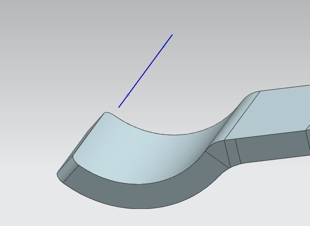
but I can't find a way to show the line that I've made- and there doesn't seem to be a method to make this line within the drafting application. If anybody could point me in the right direction I'd be grateful.
Thanks
Simon
 
Replies continue below

Recommended for you

Hi Simon,

Can you please post the image once again.

Best Regards
Kapil
 
no idea...may be it is a problem from my side only..i cannot see the image ...looks like it is blocked.
Best Regards
Kapil
 
Hi,
Could you please share the part file (if acceptable to you) ? looks like the bend part is not that cylindrical.
Best Regards
Kapil Sharma
 
Are you working in Master-Model mode (where the Drawing is actually an Assembly and your model is a Component)? If so, are you creating this line in the master piece part? If so, you will need to manually add it to the 'Model' Reference Set in that master piece part. Note that only 'bodies' are automatically added to the 'Model' Reference Set so if you need anything like curves to also be available where the Component is used, in this case in your Drawing, then you will need to add those lines to the 'Model' Reference Set yourself.

John R. Baker, P.E.
Product 'Evangelist'
Product Engineering Software
Siemens PLM Software Inc.
Industry Sector
Cypress, CA
Siemens PLM:
UG/NX Museum:

To an Engineer, the glass is twice as big as it needs to be.
 
John- very good point, and I just checked to make sure that the reference set was model. It wasn't, but changing it didn't make a difference (updated views in drafting).
 
But did you go back and explicitly ADD the line, which I assume was created in the actual detail part file, to the 'Model' Reference Set?

John R. Baker, P.E.
Product 'Evangelist'
Product Engineering Software
Siemens PLM Software Inc.
Industry Sector
Cypress, CA
Siemens PLM:
UG/NX Museum:

To an Engineer, the glass is twice as big as it needs to be.
 
John;
To be totally honest- I don't know. When I was at uni there was nothing like this sort of thing, it was mostly just sketch-> extrude, over and over! - now I've started working with NX every day, these little things pop up and have totally thrown me. what I did do with the line, was format-reference sets-click model-click line. if there's a better way of doing this that you can easily describe I'd be happy- I've managed to get my line through Kapil's instruction, but it would obviously be god to be able to put other items into sketches etc when I fancied.

Kapil- thanks very much for that. I've not optimised my face before, but it seemed to work.

Thanks both
Simon
 
No, that's about the best that you can do.

John R. Baker, P.E.
Product 'Evangelist'
Product Engineering Software
Siemens PLM Software Inc.
Industry Sector
Cypress, CA
Siemens PLM:
UG/NX Museum:

To an Engineer, the glass is twice as big as it needs to be.
 
Status
Not open for further replies.

Part and Inventory Search

Sponsor