Eng-Tips is the largest engineering community on the Internet

Intelligent Work Forums for Engineering Professionals

  • Congratulations waross on being selected by the Eng-Tips community for having the most helpful posts in the forums last week. Way to Go!

Liquid distributor head design

Status
Not open for further replies.

MIkkelPoulsen

Mechanical
Feb 1, 2023
14
DK
Hi

I working on making a simple liquid pipe head distributor design, where i'm pumping water from one tank to the top of next, and here i want to pump the water into a simple liquid distributor made of pipes with holes in.

But i do not know what speed i should calculate the hole in the pipes to - i do have some information on the water supply etc. but no experience on how to design the distributor pipe.
Any body has any experience in what speed is needed? It is not for spraying - just simple distribution over the complete area of the tank.
My values are this:
Tank diameter: ø1450mm
Water speed out of pump and into the distrubution pipe: max 3m/s (actual flow from below is: 1,3 to 2m/s) but the max allowed in the pipe system is the 3.
Pipe dimension inler: DN50
Water volume: 11-16mh3/h
Pressure: unknown at this time

How to design the nozzle pipe? I just want to make simple holes in a defined pipe size to make it simple

See picture here of the simple tanks:
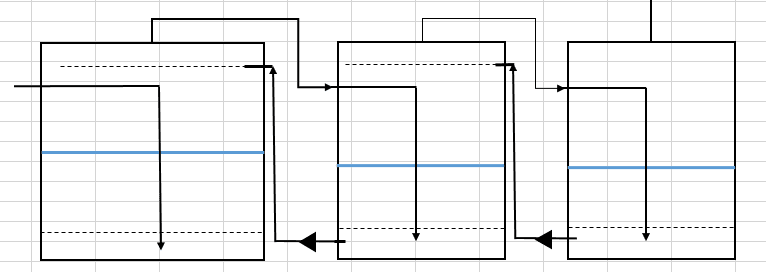
2023-04-19_10_03_46-Window_itphfu.png


And here in the top i would like to make a simple distributor like this :
[URL unfurl="true"]https://res.cloudinary.com/engineering-com/image/upload/v1681891618/tips/equipment_263695_cba54403edcb7317330b93ce8c40fd1ed20488fb_b5tet3.webp[/url]

Thanks in advance.
Best regards
Mikkel
 
Replies continue below

Recommended for you

Make the number of holes and their combined area equal to the x-sectional area of the pipe.
That will keep the spray velocity about equal to the velocity of the water inside pipe...within reason.

--Einstein gave the same test to students every year. When asked why he would do something like that, "Because the answers had changed."
 
You usually need to keep the total area of the holes slightly less than the total cross-section of the header.
This assures a more uniform backpressure across the holes and so more uniform flow from them.
The shape of holes matters also.
If you really care about distribution to also need some 'extra length' beyond the last holes otherwise you get a distinct end effect.
Most fluids handbooks have a section dedicated to distribution headers.

= = = = = = = = = = = = = = = = = = = =
P.E. Metallurgy, consulting work welcomed
 
Ed. What is the extra length about?
My fluid handbook doesn't mention this.

--Einstein gave the same test to students every year. When asked why he would do something like that, "Because the answers had changed."
 
Hi

Thanks for the feedback, i also found this yeasterday and made my calculations after this:
Link

I do not know if it is completely valid, but it seems to be used by others.
 
There is also some literature on this topic in Perry Chem Engg Handbook, in the chapter on Gas-Liquid systems Design.

Do you not also need to install a gas demister above this liquid distributor to prevent liquid drops from getting into the vapor stream travelling countercurrent to this liquid spray and out the top of each of these tanks ?
 
Extra length at the end. I worked it out. If the sum of the area of the holes is a bit less than the pipe area, that causes some liquid to accumulate in the header until pressure rises a little. Where better than at the end length. A virtual tank is created; which also stabilies flow in the last n number of holes. Kool. Never thought about that before.


--Einstein gave the same test to students every year. When asked why he would do something like that, "Because the answers had changed."
 
georgeverghese -> No because the water transfer only happens during stand still and no gasses are transported - this is purely to move the liquid from one tank to the next.

I looked in this handbook - and did not fully understand how to calculate, the other link i found was much more detailed on how to calculate the different steps.

I'm purely just interested in making a pipe sparger at the top of the tank that are distributing the water out in the complete tank area - to "wash" it down when i'm transfereing the water through the tanks anyway to kind of the clean the chemicals with clean water before all the water is transfered out of the 1 tank.
 
You might want to think about having a ring header inside the tank with nozzles / holes to run down the walls if that is your aim.

your diagram doesn't make sense by the way, but I guess that's not the point of the question.

If you want to go for a central header like you drew then I would echo the equal area or maybe area of header = 1.5 x area of the holes


Remember - More details = better answers
Also: If you get a response it's polite to respond to it.
 
Sometimes there are issues getting uniform flow because of how the end wall interacts.
If your flows are not very high then it likely doesn't matter.

= = = = = = = = = = = = = = = = = = = =
P.E. Metallurgy, consulting work welcomed
 
LittleInch

I do not want to go for a center sparger no, i was thinking about a ring or maybe divide it into 3 pipes over the area to spread it around the hole tank.
The diagram is just a fast sketch for show and explain.
 
Status
Not open for further replies.

Part and Inventory Search

Sponsor

Back
Top