I'm looking at the design shown in this video:
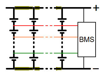
I've drawn a schematic of how I believe it works:

Essentially it's a bunch of circuit boards, with each circuit board having a string of cells in series. The boards are stacked using standoffs, which also serve as bus bars to connect all the boards in parallel. There is also a colored ribbon cable (shown at 11:00 in the video) that plugs into all the boards and connects all the corresponding cell taps together and to the battery management system.
From what I understand, it's best to first connect cells in parallel, and then connect the paralleled cells in series. This design sort of does that, but all the cells are paralleled via the ribbon cable which has very small diameter conductors. It definitely doesn't look like they could handle the full current that the cells can produce, but I'm not even sure how to estimate the current that those conductors would carry. I'm trying to evaluate this design, and that's where I'm stuck at.
Thanks in advance!
I've drawn a schematic of how I believe it works:

Essentially it's a bunch of circuit boards, with each circuit board having a string of cells in series. The boards are stacked using standoffs, which also serve as bus bars to connect all the boards in parallel. There is also a colored ribbon cable (shown at 11:00 in the video) that plugs into all the boards and connects all the corresponding cell taps together and to the battery management system.
From what I understand, it's best to first connect cells in parallel, and then connect the paralleled cells in series. This design sort of does that, but all the cells are paralleled via the ribbon cable which has very small diameter conductors. It definitely doesn't look like they could handle the full current that the cells can produce, but I'm not even sure how to estimate the current that those conductors would carry. I'm trying to evaluate this design, and that's where I'm stuck at.
Thanks in advance!
