Eng-Tips is the largest engineering community on the Internet

Intelligent Work Forums for Engineering Professionals

  • Congratulations waross on being selected by the Tek-Tips community for having the most helpful posts in the forums last week. Way to Go!

Lithium Iron Phosphate (LiFePO4) vs Lead Acid Batteries - Industrial Application & Consideration 1

Status
Not open for further replies.

Instrument1352

Electrical
Apr 9, 2014
28
0
0
AU
Hi,
we are replacing an old 30KVAh UPS system for an offshore oil installation. We have been given options of:
- Lithium Iron Phosphate (LiFePO4) Batteries; as well as
- Valve Regulated Lead Acid Batteries - maintenance free (the same as existing ones)
I am aware of the advantages of the LiFePO4 (as published online or on paper) but would like to know first hand experiences using them or probably the reason one has decided not to use them!

My concerns about LiFePO4 batteries would be:

1- Any special charging requirements. Will a typical industrial UPS (e.g. Cutler Hammer, Gutor, APM, etc.)
2- Safety and reliability. I know they are much more reliable than Lithium Ion batteries but will they be more reliable than Lead Acid batteries? In particular a risk of fire cannot be tolerated in our application.

Appreciate if you could share your experiences and thoughts on this.
 
Replies continue below

Recommended for you

A resistor will indeed control the current limiting it. But that would still be a waste of energy. I suppose you could run on one bank until you've depleted it then switch in the resistor as you switch banks then open the resistor so you never interrupt the battery power to the UPS.

I'd just diode AND the two battery strings together. This would have them both always ON line. Nothing needs to switch, nothing to fail. They would be completely unable to cross charge each other. Both would drain uniformly into the UPS. If one happens to have a higher potential than the other it will win the ANDing and be the supplier until the two banks come into parity then it they both will provide about the same as they both slowly discharge.

Diode ANDing is what's used for redundant power supplies in critical systems because a diode is so simple as to be much more dependable than any other possible scheme.

I would use two separate chargers since chargers are capable of screwing things up rather easily you don't want one screwing up BOTH banks. Also two can be wired so if one chokes (and they do!) the other could be pressed into charging both banks alternatingly while servicing the failed charger.

Question is how much current will your UPS demand from a 120Vdc source?

Keith Cress
kcress -
 
Using the diode will have the challenge of charging as we have a single charger only. We have two strings of 120V and the continuous current will be about 150A per string. (120*150*2*0.85=30KW with an assumed UPS efficiency of 0.85)
 
So far every dual-string application I've come across has simply paralleled two identical strings. I agree that if they're in a significantly different state of charge then things could get exciting. In that case I would probably separately charge each string fully prior to paralleling. The UPS can be put to bypass for the brief period for changeover.
 
Simply string paralleling is just SO lame it astounds me. Anything shorts a cell in one string and besides that string dropping, the other string is dragged down blowing charge into the problem. Absolutely a pointless waste!

I had a parallel stack, one cell shorted in one bank the other bank dumped into the partially shorted one and the charger tried to bring up the 'dead battery' and in 5 minutes the string with a shorted cell in it was boiling furiously with steam, hydrogen, and oxygen pouring out of it. You could hear it boiling from a distance. The battery case was blazing hot. It was frankly... terrifying.

So, put in a fortune of batteries to keep a critical system up, skip the $100 diodes because we're too cheap to use two chargers as you should. You've just lowered the system reliability by 50%.

You might as well directly parallel all the batteries. Don't separate them into strings. Don't forget the fuses.

Keith Cress
kcress -
 
Yes, the strings are fused separately in case of a major fault - should really have said that.

Most VRLA failures I've seen have been high resistance or thermal runaway (melted casing) - haven't in person seen one go short yet.
 
All the big charging applications I've come across use modular charger units and a communications medium for the modules. Effectively its a single big charger, but they've all had some level of redundancy in terms of charging modules and failure modes. I'd have to trawl through my records as to how they managed different strings paralleled together but its certainly possible.

LEM among others sell string monitoring equipment, so its then possible to identify the failed string (or cell, depending on how its done) and then drop the offending string. It does require rated DC contactors or breakers though.

EDMS Australia
 
Keith,
I do understand the potential issues and fully agree with the catastrophic failures you suggested. I have used modular chargers before (as Freddy has suggested), but in this case we have a UPS with single charger and single inverter.
I am trying to figure out how to use diodes to fix the problem, however I struggle to understand how that might work with single charger. The terminals to charge the batteries (from the charger) are the same as those to use the batteries (to the inverter). Could you please explain how the diodes can be used?
Thanks
 
Ah.. I see your problem.

That makes it more complex. It can still be done but the complexity reduces the reliability.

With that handicap I recommend you simply parallel each battery to its neighbor. I use a fuse between each paralleled battery so if one shorts a cell it gets disconnected leaving all the rest of the batteries intact.

Keith Cress
kcress -
 
Breakers can work but personally I'd not use them in this case only. Breakers tend to cost way more in DC breaker land than fuses. They often are a little more difficult to mount and wire then fuses in battery settings, possibly increasing cable run lengths, that are always detrimental in battery systems.

Example comparisons

When you use anything for interruption you need to check what the available fault current maximum is. With big batteries it's not hard to end up with a breaker that can't actually interrupt the available fault current. The last system I did I wanted to be able to cut out a battery. They were ALL paralleled so cutting one out didn't do anything other cut out UPS time. Turned out I could use beakers for each of the batteries but there were no breakers that could disconnect them all at once from the UPS since the fault current was astronomical. I used a fuse instead.

Keith Cress
kcress -
 
Thanks again to all of you who contributed to my query. Special thanks to Keith and Scotty.

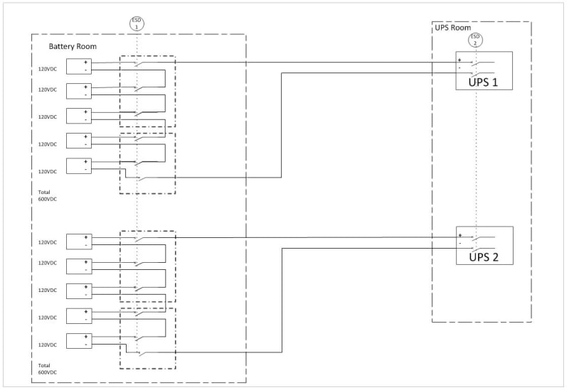
I ended up using an N+1 (in this case N=1) redundant UPS with one common bypass, two supply feeders, two rectifiers, two inverters, two battery banks each with their own cables and DC breakers with shunt trip and one common output side bus. During the normal operation each will have 50% of the load. In case one set fails the other will take over 100% of the load. At any time each one of the UPS can be isolated and worked on (with work procedure and LOTO of course).

 
Hi Keith & Scott,
Here is a sketch I made for you:
I did not sketch the full UPS side as it is a standard N+1 topology as I explained in my previous post. If we loose independent side e.g. a battery string, say faulty cell, or one inverter, etc. the other UPS will still provide the supply, albeit with reduced autonomy time.

From the charging profile, the UPS will pick if the battery is faulty. The circuit breaker in the battery room will also provide some protection against a short circuit of part of the string to chassis. Also it breaks the string into 120V segments which makes it easier in certain fault cases also makes working on batteries easier.

Cheers,
Hammet

UPS_Config_2019_Capture_lnmyar.jpg
 
An interesting couple of follow-ups:
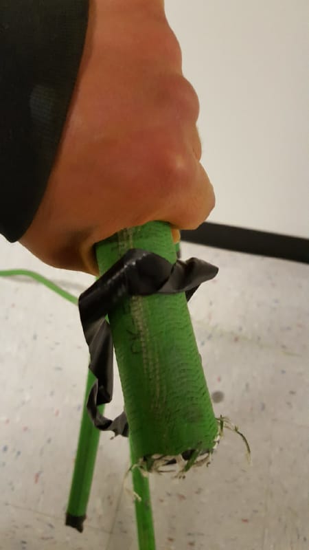
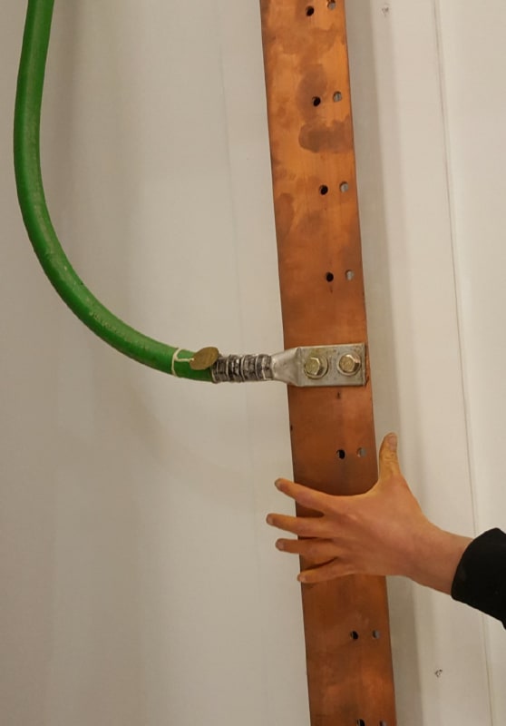
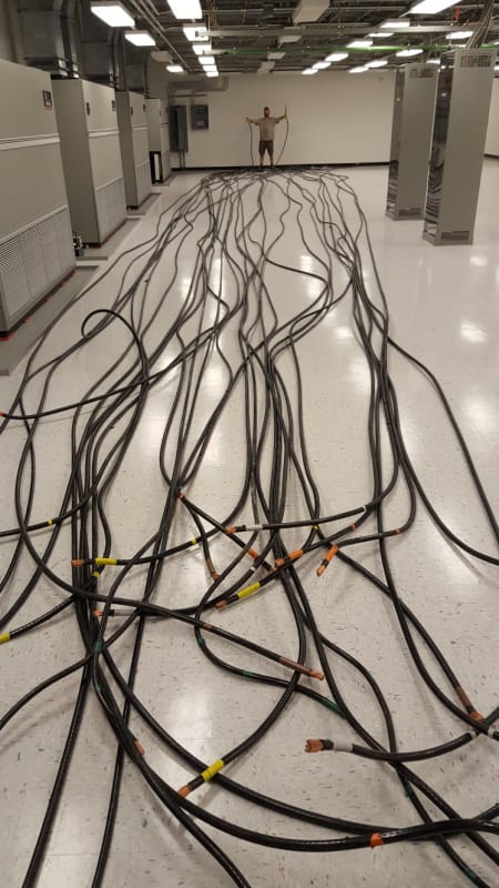
Remember these things I put up in ~3 threads?

20190129_212646_MCM1000_ground_cable_pjvpae.jpg


20190129_212654_Ground_BB_d7uqkq.jpg


thread238-448323

20190129_205840_h5tsq3.jpg


They finished scrapping out the copper from this battery backed server farm and told me about the results yesterday.

The 1.5MW Cat Generator was removed. It took a 240 ton crane and a second semi loaded with weights to lift it to a low-boy.

The copper included the cable above and much more. 22,000 pounds of busbar alone. Total of $82,000 in scrap copper and transformer iron.
I had no idea. Too bad I didn't get a cut.
6bm5afp.gif


Keith Cress
kcress -
 
I was told $2.20/pound for pure copper like the bus bar. Then there are two discounters. Thick insulation and thin insulation. The cable shown above on the floor reduces the $2.20 down to 90% and the green stuff with much thicker insulation down to 82%.

Keith Cress
kcress -
 
Status
Not open for further replies.
Back
Top