Continue to Site

Eng-Tips is the largest engineering community on the Internet

Intelligent Work Forums for Engineering Professionals

  • Congratulations KootK on being selected by the Eng-Tips community for having the most helpful posts in the forums last week. Way to Go!

Load bearing capacity of a 40' seacan

Zoobie777

Chemical
Jun 28, 2022
21
I have designed several roof truss systems for garages/storage buildings constructed with seacans as the 'walls'. They are increasingly popular, especially with homesteaders. Most of the time the trusses bear on the walls with a sill plates running up the 40' (or 20') sides. We have a customer asking for a 4' spacing option for a roof with a 40' clear span between the containers. This is resulting in bearing reactions on the inside bearings of 5200 lbf unfactored/7300 lbf factored. While the building design is outside of my scope, I am wondering if there is a maximum point load for this type of construction. Will a single or double SPF plate distribute the load sufficiently? I found out what the weight of a seacan roof can hold (~57000 lbs) but not sure how that translates into max plf for the wall. Also, is there an appreciable difference in capacity between a normal seacan (8'-6" tall) and a high cube (9'-6" tall)?

Thanks for any info/advice you may have.

Cheers!
 
Replies continue below

Recommended for you

It's extremely unlikely that the roof of a sea can is good for 57,000 pounds, so that's my first piece of advice. You stack seacans on top of each and they need to bear on the walls of the sea can below, that might be where you get the 57k from. I'd guess the whole project is outside of your scope, try and find an off the shelf solution like this https://www.futurebuildings.com/steel-building-types/container-covers.html
Where someone will take all the liability.
 
Many years ago I looked into sea-can structures for a bit, from memory I think the roof could support ~30psf.
In their normal use case most of the load is transferred through the columns in the corners. I would be concerned if your bearing line doesn't align with the wall of the sea-can
 
It's extremely unlikely that the roof of a sea can is good for 57,000 pounds, so that's my first piece of advice. You stack seacans on top of each and they need to bear on the walls of the sea can below, that might be where you get the 57k from. I'd guess the whole project is outside of your scope, try and find an off the shelf solution like this https://www.futurebuildings.com/steel-building-types/container-covers.html
Where someone will take all the liability.
As I mentioned, the building design is not in my scope...just the trusses. I am just curious and trying to build some knowledge with the help form others.
 
Many years ago I looked into sea-can structures for a bit, from memory I think the roof could support ~30psf.
In their normal use case most of the load is transferred through the columns in the corners. I would be concerned if your bearing line doesn't align with the wall of the sea-can
Thanks. The load will be bear on one wall (the inside wall) and I assume a 2x6 plate will be on top of the seacan wall to secure the trusses. The outside wall will see an uplift from the trusses. The loads on the inner wall are 463 plf DL and 814 plf SL. This is not high at all for a wood framed structure with 24" oc truss spacing and I expect the seacan can support this no problem. My question/concern, which is not my scope but has me curious, is what happens if the spacing is now 48" oc and each truss has a unfactored reaction at the wall of 1882 lbs DL and 3290 lbs SL. If this were a regular wood framed structure you probably would have at least a stud if not a column under this (or a beam). Just wondering if a seacan can take this kind of point load. I have been in many a seacan but TBH I have never looked at the structure.
 
 
So just for those who couldn't be arsed following the links,

The corner posts are the main structural elements, the design standards are performative, not specific and the design are down to each vendor.

So look closely at each container.

Many cross beams seem to be 60mm 3mm thk square tubes. Analyse that ignoring the rather thin steel cladding.

The roof structure itself is often pretty weak and many designs of container have no roof.

Are these trusses spanning a container? A drawing would be nice to see.
Since the corner posts support the units above, the only way these containers work is the sides are deep diaphragm beams with the cladding for the webs. I'd love to see the analysis on one of these. I imagine the small top beam will distribute the load adequately into the deep beam.
 
From my container notes:
CONTAINERS

-ALL CONTAINERS SHALL BE SIMILAR SIZE, WEIGHT AND CONSTRUCTION.

-CONTAINERS SHALL BE FABRICATED TO ISO 1496-1990 EDITION MINIMUM.

-CONTAINER DESIGNATION SHALL BE 1D OR 1DX MINIMUM.

-CONTAINERS SHALL BE MINIMUM GRADE B, THESE ARE GENERALLY CONSIDERED AS CONTAINERS HAVING A FEW DENTS AND SCRATCHES, BUT CAN BE USED FOR STORAGE. THEY SHOULD NOT HAVE SUSTAINED MAJOR DAMAGE OR HAVE SIGNIFICANT CORROSION.

-CONTAINERS SHALL BE CERTIFIED AS CARGO WORTHY (CWO) AND WIND AND WATERTIGHT (WWT).

-CONTAINERS SHALL PASS THE FOLLOWING TESTS STIPULATED IN ISO 1496, U/N:

TEST 01- STACKING;

TEST 02- LIFTING FROM THE FOUR TOP CORNER FITTINGS;

TEST 03- LIFTING FROM THE FOUR BOTTOM CORNER FITTINGS;

TEST 04- RESTRAINT (LONGITUDINAL);

TEST 05- STRENGTH OF END WALLS;

TEST 06- STRENGTH OF SIDE WALLS;

TEST 07- STRENGTH OF ROOF;

TEST 08- FLOOR STRENGTH;

TEST 09- RIGIDITY (LONGITUDINAL);

TEST 10- RIGIDITY (TRANSVERSE);

TEST 11- LIFTING FROM FORKLIFT POCKETS;

TEST 12- LIFTING FROM THE BASE AT GRAPPLER ARM POSITIONS; AND

TEST 13- WEATHERPROOFNESS;

-IF LIFTING FROM THE FOUR BOTTOM CORNERS ONLY COMPLIANCE WITH TEST 02, TEST 11, AND TEST 12 CAN BE WAIVED.

-IF LIFTING FROM THE TOP CORNER CASTINGS COMPLIANCE WITH TEST 02 IS REQUIRED.

-THE FOLLOWING COATING SYSTEM IS RECOMMENDED. CLEANING SHALL BE TO SSPC-SP 1 AND SSPC-SP 6. PRIMER SHALL BE DEVOE 'DEVGUARD 4160 - MULTIPURPOSE TANK AND STRUCTURAL PRIMER'. TOPCOAT SHALL BE DEVOE 'SPEEDENAMEL 4318 - QD GLOSS ENAMEL' . COLOUR SELECTED BY OWNER.

-CONFORMANCE WITH ANY MECHANICAL OR ELECTRICAL REQUIREMENTS OF THE NATIONAL BUILDING CODE HAS NOT BEEN REVIEWED.

-CONFORMANCE WITH ANY REQUIREMENTS OF THE NATIONAL ENERGY CODE HAS NOT BEEN REVIEWED.

-CONTAINER DESIGN LOADS:

A 40’ SHIPPING CONTAINER HAS A TARE WEIGHT OF ABOUT 8159LBS AND A MAXIMUM CAPACITY OF ABOUT 59,039LBS. THE MAX LADEN WEIGHT IS ABOUT 67,199LBS.

Ss = 1.9KPA;

Sr = 0.2KPA;

q (WIND) = 6.4PSF (BASED ON 5 YEAR RETURN PERIOD, CALCULATED USING THE BC BUILDING CODE METHOD. IN THE EVENT OF A PUBLIC WEATHER ALERT FOR A SEVERE STORM EVENT, FROM ENVIRONMENT CANADA, PEOPLE SHALL DISTANCE THEMSELVES FROM THE SCREEN LOCATION;

Cg = 2;

Ce = 1;

Cp = 0.8 (WINDWARD);

Cp = 0.5 (LEEWARD);

CONTAINER WEIGHT = 5000 LBS MIN FOR 20’ CONTAINERS; AND

CONTAINER WEIGHT = 8250 LBS MIN FOR 40’ CONTAINERS.

-CONTAINER ATTACHMENT SHALL BE ACHIEVED BY USING METAL BANDING OR STRAPS FABRICATED FOR THIS PURPOSE.STRAPS SHALL BE PLACED AT 1/5 THE CONTAINER LENGTH FROM EACH END AND SHALL DEVELOP THE FOLLOWING MINIMUM LOAD CAPACITIES:

TOP CONTAINER TO INTERMEDIATE CONTAINER = 1000 LBS; AND

INTERMEDIATE CONTAINER TO BOTTOM CONTAINER = 2800 LBS.

-DEADLOAD, UNSHIFTABLE BALLAST SHALL BE PROVIDED FOR THE BOTTOM CONTAINERS. PROVIDE 64 PSF BALLAST FOR THE 20’ CONTAINERS, AND 82 PSF FOR THE 40’ CONTAINERS. THE AREA IS BASED ON INTERIOR FLOOR AREA OF THE LOWEST CONTAINER.

-CONTAINERS SHALL BE FOUNDED ON A GOOD COMPACTED GRANULAR BASE HAVING A BEARING RESISTANCE OF 2000 PSF MINIMUM.

-CONTAINER SUPPORT STRUCTURE IS INTENDED FOR SHORT DURATION LOADING ONLY AND NOT FOR OPERATION DURING THE WINTER SEASON.

-THE SCREEN SUPPORTING TRUSSES, SUPPORTED ON THE TOP HAVE BEEN REVIEWED FOR STATIC LOADS ONLY. THEY SHALL NOT BE SECURED AT THE BASE (THIS WILL INCREASE THE VERTICAL LOADING ON THE TRUSSES. THE ENDS OF THE TRUSSES SHALL BE SECURED TO THE CONTAINERS AND SUITABLE BEARING PROVIDED.

You need to get a copy of ISO 1496.
 
So just for those who couldn't be arsed following the links,

The corner posts are the main structural elements, the design standards are performative, not specific and the design are down to each vendor.

So look closely at each container.

Many cross beams seem to be 60mm 3mm thk square tubes. Analyse that ignoring the rather thin steel cladding.

The roof structure itself is often pretty weak and many designs of container have no roof.

Are these trusses spanning a container? A drawing would be nice to see.
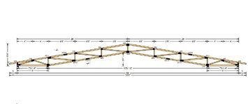
Attached is a picture of the truss. The bearings are aligned with the walls of the seacans. From my understanding, people put a 2x plate along the top of the walls. This is a much larger span than what we normally design so in this case there is a large 1000lb+ uplift (with 24"oc) on the outside wall.
 

Attachments

  • Truss.pdf
    50.9 KB · Views: 11
That's pretty big. Not sure a 60mm square tube, especially 40 ft long, is going to like that.

You might need to start thinking about reinforcing it with some vertical posts inside I r outside the container.

Here it is for others.


Screenshot_20241116_125955_Drive.jpg
 
I'd be careful putting the load down on both walls of the can... maybe have a support between the walls.
 
I've attempted something similar and, in my opinion, it really cannot be made to work by the book.

As far as downward load goes, your 2x plate(s) will be completely ineffective as far as load distribution goes. That, because their stiffness will be dwarfed by that of the side walls.

And the same will hold true of the container top rail really. I believe that the top rail's job is really just to deliver uniform roof loads to the side walls without introducing too much localized for or eccentricity. As others have said, the only structural members of significance in these things are the corner posts. And, to a lesser extent, the beams at the front and back of the containers.

Where your trusses touch down, there will be a point load on the corrugated side wall. Your failure mode will be local buckling of the corrugated side wall. If you double the spacing of the trusses, that point load will double +/-. If the trusses are close enough you'll get some benefit from overlapping side wall buckling patterns but that will be very difficult to account for.

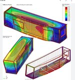
I watched a neat AISC webinar on the design of shipping containers by Socrates Ioannides. You can do some neat stuff with them but it's FEM heavy. Mostly, what I learned is that I don't want to work with seacans.

c01.JPG
 
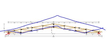
I would be inclined to design your trusses to not utilize the exterior bearings. Those will be difficult to hold down and will amplify the load at the interior bearings.

c01.JPG
 
I would be inclined to design your trusses to not utilize the exterior bearings. Those will be difficult to hold down and will amplify the load at the interior bearings.

View attachment 1206
I imagine the truss company is trying to use that couple to make the trusses more efficient. I would be curious how much heavier they get with only the inside bearing.
 
I watched a neat AISC webinar on the design of shipping containers by Socrates Ioannides. You can do some neat stuff with them but it's FEM heavy. Mostly, what I learned is that I don't want to work with seacans.

Same here!
 
I imagine the truss company is trying to use that couple to make the trusses more efficient.

Maybe. Often these things are in such locations that depth is almost a non-issue. @Zoobie777: what say you?

One also has to weight the cost of sturdier truss against the cost of the hold down situation.
 
I suppose another thing to watch is to make sure the thrust at the truss bearings doesn't just push the seacans over.
 

Part and Inventory Search

Sponsor