Continue to Site

Eng-Tips is the largest engineering community on the Internet

Intelligent Work Forums for Engineering Professionals

  • Congratulations SSS148 on being selected by the Eng-Tips community for having the most helpful posts in the forums last week. Way to Go!

Load distribution between PEMB portal frames and anchors 2

Status
Not open for further replies.

RabitPete

Structural
Nov 24, 2020
109
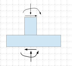
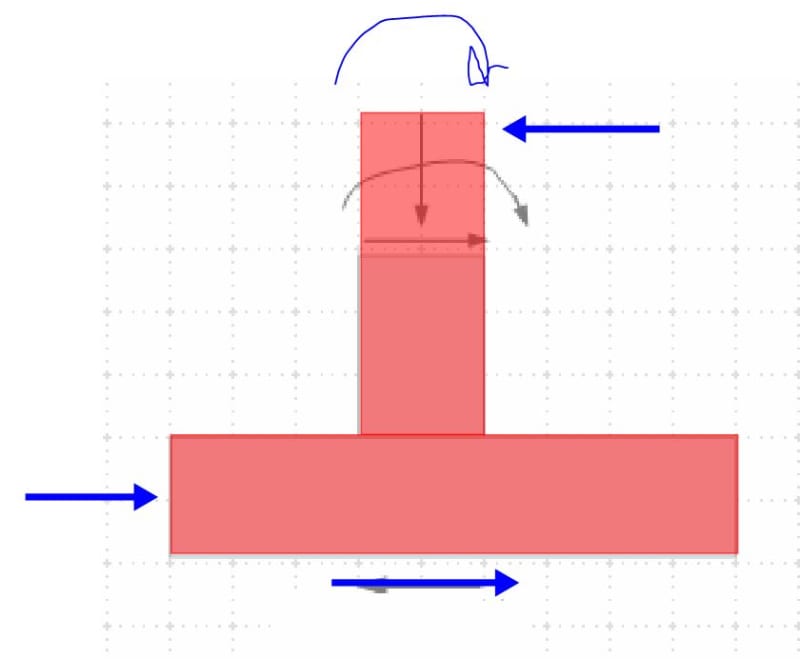
It might seem a like a silly question, but for some reason I am stuck thinking about it. Lets consider a typical PEMB portal frame designed to handle lateral loads. It is always designed with columns pinned at the base. However in reality those anchors will develop some moment capacity, and certain minimum is even required to satisfy OSHA rules. How do we prevent lateral loads from loading those anchors? I modelled the connections and then used resultant stiffness to analyze moment frame instead of using pined ends. Turned out a substantial moment (nearly a third in my example) is transferred to the foundation which nobody ever designs to resist.

Since anchorage was not designed to handle that much of a moment, would not it fail first, before the moment frame takes on the full load? And at that point compromised anchorage can no longer resist shear forces it was designed for? Or is it assumed that with enough ductility, anchorage stiffness will decrease drastically once inelastic region is reached and nearly full load will redistribute back to the moment frame? If that is the case, would not it cause a fatigue failure after repetitive cycles?

 
Replies continue below

Recommended for you

It's not a silly question. For moment frames, this is something I typically have a look at. But a lot of people (I think) tend to overestimate the rotational stiffness....ergo, they get more moment than will be there.

For certain SDCs (Category C or higher), the overstrength factor is used.....so that helps for people who don't worry about this stuff.
 
I agree it's not a silly question. Indeed the fact that you're asking it shows that you want to understand what the building is doing and not just cookbook your way through your career - good on ya.

WARose brings up the key point - rotational stiffness. Or, rather, relative rotational stiffness. When you consider the frame as a whole, what is the stiffest connection point? It's typically at the eave in a PEMB. That's often the most robust moment connection. Depending on the size of the building, you could have a bolt group with 8 or 12 high strength bolts resisting tension, and a 36" moment arm within the connection. Then look at the base. The frame tapers down to an 8" depth with 4 anchors spaced 3" apart. The upper connection is so much stiffer that the resistance will occur there. That's why, even when they have straight leg frames, the anchors are still typically only 3" apart and set out toward the edge of the building.

Add to that the foundation. If you analyze the base as pinned and give it a little footing only large enough to resist the uplift (granted, that can still be a gargantuan footing in a PEMB), then the footing itself can move some when the small amount of actual fixity at the base is mobilized. This further redistributes that moment up to the upper frame connection.

This is why it's so important to ensure that the detailing matches realty. Call a connection pinned in the model but then make it a moment connection, and your structure won't behave as you assumed. But make it a pin and then detail it as a pin, and you'll get predictable behavior.
 
Yep. This is one of the most common 'mistakes' in connection design. I say 'mistakes' because many times you can readily get away with it, until it comes and bites you.

In the case of a typical footing in a PEMB if it does receive excess moment there is often additional flex in many parts of the connection and if not the connection then the footing itself could rotate slightly causing cracking in the slab. Outright failure is unlikely to occur as once you get a bit of flex the load then increases on the structure as the connection is now behaving more like a pin.
 
You might try to footing on compression springs. I think that you will find that it allows quite a bit of rotation, even with the column base “fixed”.
 
I guess soil behavior is what I was missing. My model had a rotational stiffness for the eave and baseplate connections, but did not include the pedestal, pedestal to footing connection and footing/soil interaction. All those will add some flex and moment will probably redistribute more towards the eave connection
 
Adding pedestal made things worse, as pedestal is much more rigid than a column it supports and shear multiplied by the pedestal height now adds up to the moment at the footing, further increasing eccentricity and soil pressure, which all make sense.

Software we have only has a torsion spring option as a node restraint, so next I tried calculating rotational stiffness of a footing. From what I understand, Kf=Ks*If, so for sample 48" square and 300 psi/in subgrade: If =B*H3/12=442,368 in4 and Kf=132,710,400 lb-in/radian or 11,059 kip-ft/rad. Sounds an awfully large number. Am I doing something wrong?

Or its probably not such a straight forward calculation, and as moment increases, loading becomes more and more eccentric and smaller and smaller area of the footing is in contact with the soil, so "If" decreases significantly until balanced state is reached, where actual If=B*Hactive3/12+B*Hacive*(H/2-Hactive/2)2

bear_jlkway.png
 
At a minimum, the forces on the footing should be balanced, no matter how you analyze it. The capacity of the footing is determined by the strength of the soil, and the size of the base plate/slab. For gravity load cases, you should aim to have resultant force stays within the kern. As the eccentricity increases, yes, as in your sketch, part of the footing can lose contact with the soil, and is considered inactive.

image_agxs3i.png
 
I did a few iterations going back and forward between my spread footing calculator and frame analysis software and found a rotational stiffness which results in a balanced solution. And seems like over 90% of the moment is handled by the eave connection and indeed very little is carried down to the foundation. And while it is still somewhat approximate method, assuming my expression for "If" is correct, results do make sense.
 
Software we have only has a torsion spring option as a node restraint, so next I tried calculating rotational stiffness of a footing. From what I understand, Kf=Ks*If, so for sample 48" square and 300 psi/in subgrade: If =B*H3/12=442,368 in4 and Kf=132,710,400 lb-in/radian or 11,059 kip-ft/rad. Sounds an awfully large number. Am I doing something wrong?

That sounds like it's in the ballpark. I'd backcheck via Bowles. (I don't recognize your formula.) There is a formula in there for static rotational stiffness.

I'd choose a range of values for that by the way. Whatever value you calculate....the real value will not be exactly that. (Due to the variability of soils.)
 
RabitPete said:
I did a few iterations going back and forward between my spread footing calculator and frame analysis software and found a rotational stiffness which results in a balanced solution. And seems like over 90% of the moment is handled by the eave connection and indeed very little is carried down to the foundation. And while it is still somewhat approximate method, assuming my expression for "If" is correct, results do make sense.

Nice! It sounds like you've done the grunt work and proven to yourself what I and others have alluded to.

I'm losing count of the number of times which I've done similar on various conundrums discussed on this forum. Lots of things do just simply balance out in the end. But it is worth doing the exercise so you know what matters and what doesn't.
 
Thanks, Ron.

Good work, RabitPete. It's good to go through those exercises - and unfortunate that most of them have to be done on our own time. My employers never had the budget to actually explore those nuances. Thanks for sharing the results with everyone else.
 
Some words of caution with respect to the modelling:

1) With respect to shallow foundations, geotechnical information is generally provided assuming:

a) that settlement rules and low moduli are conservative.

b) loads are slowly applied and sustained for long periods.

If you tell your geotech that you're designing for short duration, reversible loading in a situation where excess soil stiffness is bad, you can easily get moduli recommendations a full order of magnitude higher than those you'll get for typical, long term, settlement dominated problems.

2) Be wary that, depending on your details, there may be mechanisms of base fixity other than just the soil spring thing. In places like Alberta and Wisconsin, the underside of the footing is likely to be five feet below adjacent grade level which sets up the mechanism shown below. And that mechanism will be pretty stiff right up until static soil friction is overcome.

3) With respect to meaningful flexibility, my money's on the base plate connection itself. There are some nifty European methods for assessing this but, in my opinion, it's still too rough to provide reliable quantification in many practical situations.

C01_om9inu.jpg


c02_zavoex.jpg
 
Good point on depth of the footing, KootK. Where I am, frost depth is about 8" so most PEMB foundations I design are actually above grade. Depending on where the OP is in Indiana, it could certainly have a very meaningful impact on footing rigidity.
 
Yes, very good point. I was taught to never count on any lateral soil resistance or soil weight while designing spread footings for PEMBs, so I naturally ignored it.

 
Status
Not open for further replies.

Part and Inventory Search

Sponsor