Tygra_1983
Student
Dear all
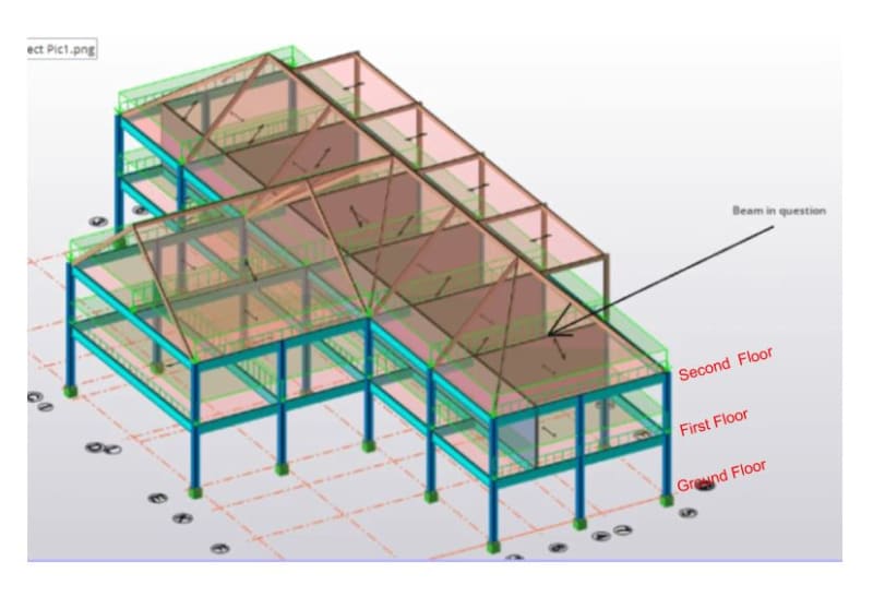
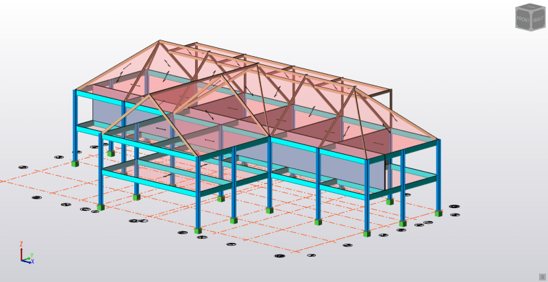
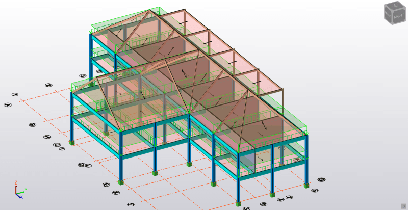
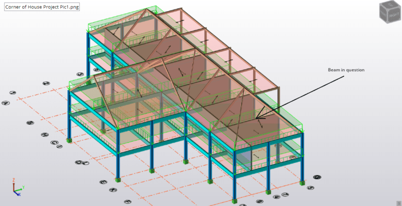
I am currently working on a hypothetical project for the following structure:
Firstly, I am tackling the load distrubtion on beams in kN/m from an applied area load in kN/m^2. I am analysing the load that comes from the floors including the imposed load which is 2.95 kN/m^2. You can see how the load is distrubited in the following figure:
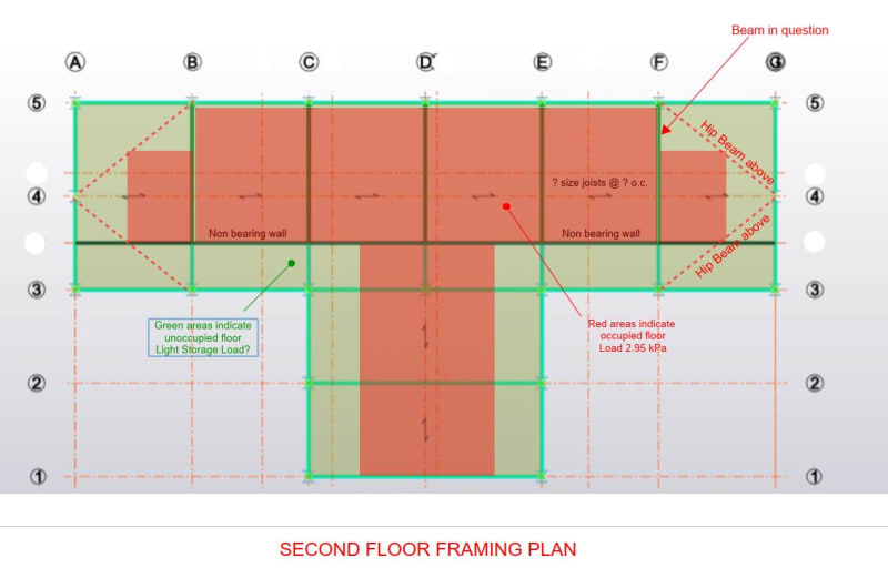
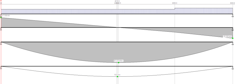
I am confused how the load has been distrubuted to the following beams. The distributed load changes after the intersection of the wall.
To get the UDL I multiply 2.95 kN/m^2 by 5m (the panel widths) which gives 14.75 kN/m. However, this load does not extend across the whole beam. It reduces to 11.8 kN/m.
I guess the wall has something to do with this change in load, but I don't know why. When I look on the plan I feel that the beam should be 14.75 kN/m all the way along the beam; that is the area load should be multiplied by the panel width to get the load in kN/m.
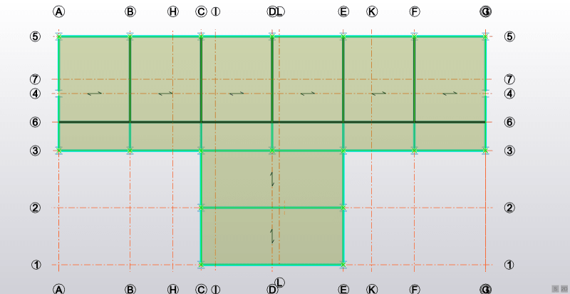
Why is this happening? Thank you in advance and I hope I have explanied myself clearly enough.
I am currently working on a hypothetical project for the following structure:
Firstly, I am tackling the load distrubtion on beams in kN/m from an applied area load in kN/m^2. I am analysing the load that comes from the floors including the imposed load which is 2.95 kN/m^2. You can see how the load is distrubited in the following figure:
I am confused how the load has been distrubuted to the following beams. The distributed load changes after the intersection of the wall.
To get the UDL I multiply 2.95 kN/m^2 by 5m (the panel widths) which gives 14.75 kN/m. However, this load does not extend across the whole beam. It reduces to 11.8 kN/m.
I guess the wall has something to do with this change in load, but I don't know why. When I look on the plan I feel that the beam should be 14.75 kN/m all the way along the beam; that is the area load should be multiplied by the panel width to get the load in kN/m.
Why is this happening? Thank you in advance and I hope I have explanied myself clearly enough.