Hello!
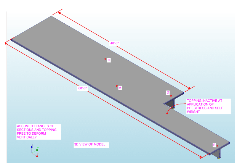
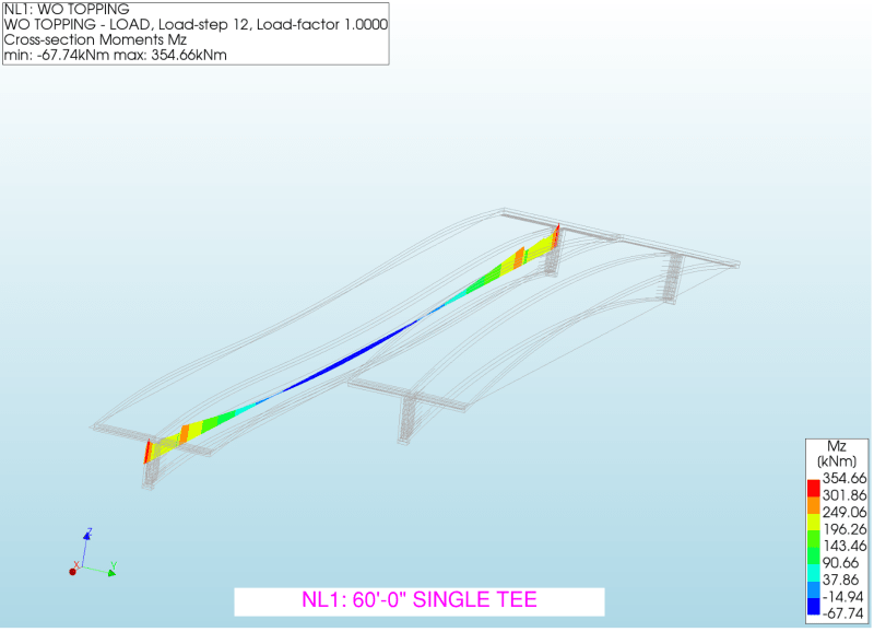
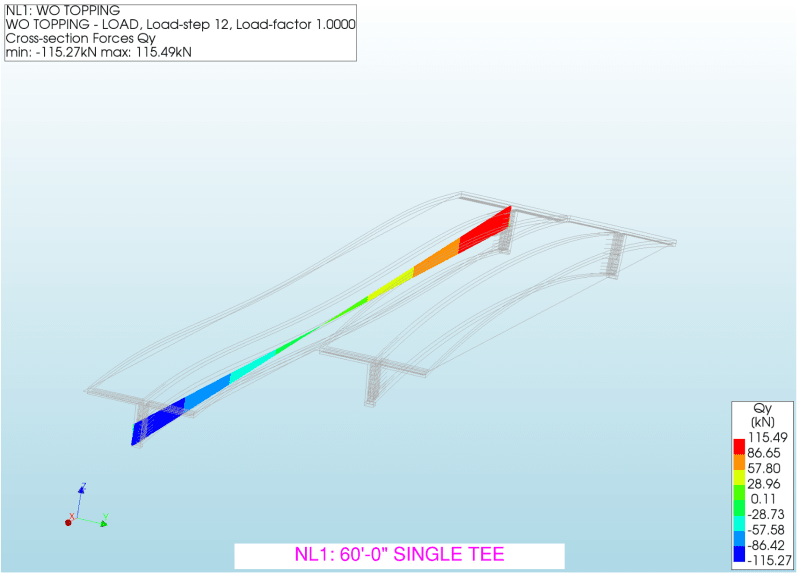
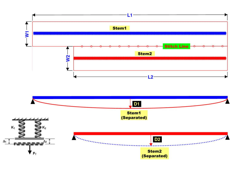
Let's assume two single stem Tees (independent L1xW1 and L2xW2) are combined rigidly into one double tee
along the stitch line.
I wonder how a load will be distributed to each stem.
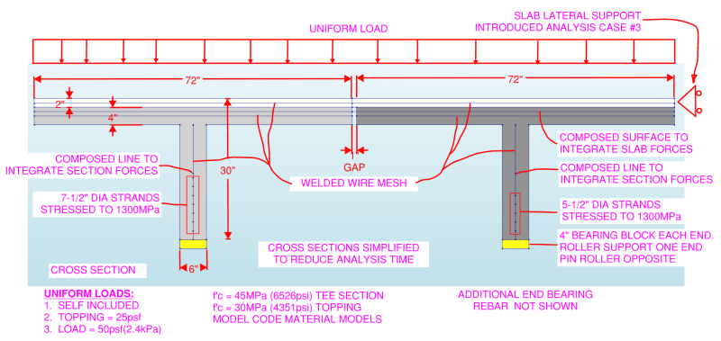
Do you think a load will be transferred according to the stiffness (k1, k2) of each stem?
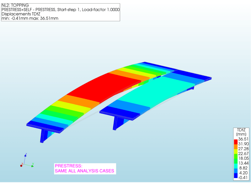
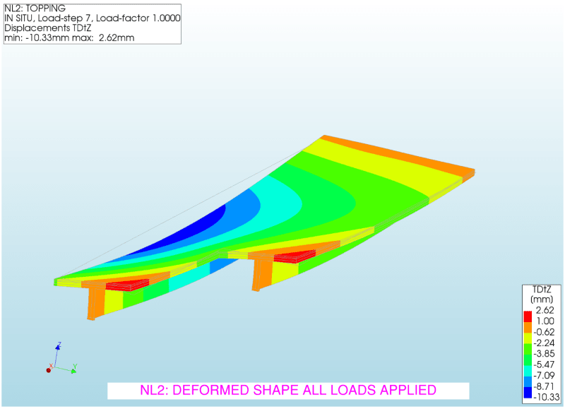
Also, how can I find the maximum deflection points?
I guess the largest deflection points will be different from the midpoints, L1/2 and L2/2.
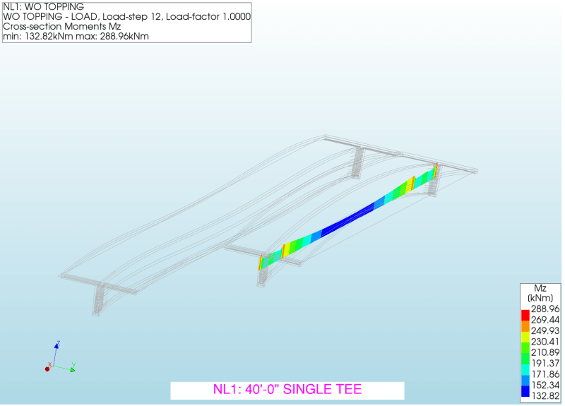
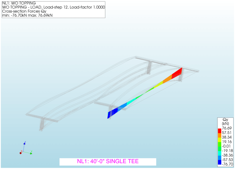
Let's assume two single stem Tees (independent L1xW1 and L2xW2) are combined rigidly into one double tee
along the stitch line.
I wonder how a load will be distributed to each stem.
Do you think a load will be transferred according to the stiffness (k1, k2) of each stem?
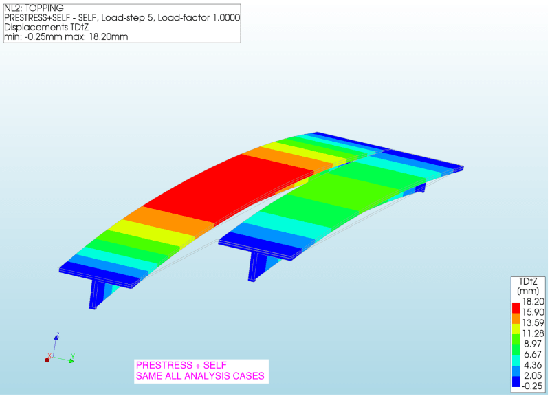
Also, how can I find the maximum deflection points?
I guess the largest deflection points will be different from the midpoints, L1/2 and L2/2.