Continue to Site

Eng-Tips is the largest engineering community on the Internet

Intelligent Work Forums for Engineering Professionals

  • Congratulations waross on being selected by the Eng-Tips community for having the most helpful posts in the forums last week. Way to Go!

Load NASTRAN structural results for Thermal Analysis

Status
Not open for further replies.

chamansrv

Materials
Jul 7, 2015
20
Hello,

Is there any way to upload NASTRAN structural results, as a precursor for another analysis (in my case thermal analysis).
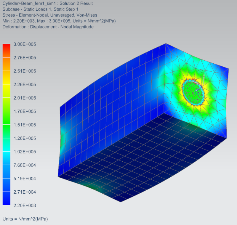
2015_08_05_13_55_41_NX_10_Advanced_Simulation_Simulation_Cylinder_Beam_fem1_sim1.sim_Modifie_jnuito.png

I'm attaching a picture of my deformed structure. Now I want to cool this sample from this deformed state. I can do this in NX thermal, but I'm not sure how to upload the output files of this deformed state.


Regards
Chaman
 
Replies continue below

Recommended for you

Hi Chaman,

This is some old documentation that I did few years back, attached as for your reference.
The idea is as below:
1. From the structural analysis, extract the coordinate changes of each grid/nodes.
2. The extracted information is put into a template (in my case the excel sheet). This template serves to re-write the input file (.dat) of Nx Nastran. By using this template, the new grid format is obtained.
3. In the old input file, delete all the grid/node cards, then replace it with the new grid cards.
4. Save the new input file.
5. Export the input file into NX again.

There might be newer and easier way to do it. I remember seeing NX obtaining the new deform CAD model (not just the mesh), based on the structural deformation analysis. Hope someone can share too..

Regards,
Tuw
 
 http://files.engineering.com/getfile.aspx?folder=a8c1a96b-bb4b-4988-9f56-18e81eede58d&file=NX_Deformed_Mesh.zip
Dear Tuw,

This method seems to be working but the results are not as expected. I think they changed something in NX10. I'm waiting for other opinions as well. If you know any other option, please let me know.

Thanks and Regards

Chaman
 
Dear Expert Tuw,

1. The script in the 2nd Deformation .xlsx file seems to be a good option. Can you explain in brief, what is the basis of this script? My model in the picture above has a surface contact.
2. When a non-contact model is used, the result is shown below:

2015_08_10_15_55_02_NX_10_Advanced_Simulation_Simulation_Cylinder_Beam_sim1.sim_Modified__e5wgwi.png


I tried to export the displacement iteration results for a new study but the results turn out to be completely bizzare. I have tried to use standard/extended post processing export options. This is how the new exported model looks like.

2015_08_10_15_56_23_NX_10_Advanced_Simulation_Simulation_cylinder_beam_sim1_structural_new_s__bpwtc2.png


What are your opinions on this.

Hoping a reply.

Regards
Chaman
 
Hi Chaman,

The objective of the script is just to get the new deformed mesh. The by product however (when you import the modified input file back to NX), are such as boundary conditions, loading conditions etc, probably are not really what you want, thus you can ignore those, and re-create the loading and boundary conditions.

If you look at my excel file, there are 2 columns of GRID cards, you will need to copy both columns into the input file. The grid card always use large field format (16 spaces for each coordinates value) in order to precisely capture the coordinates. Therefore, for each grid definitions, 2 rows are required.
15s24br.png


From your first figure and second figure, you are saying that the cylindrical object is not the same size?

Regards,
Tuw
 
Dear Tuw,

Thanks for the explanation.

I'm following the procedure you suggested in the presentation. For my analysis, I would like to import the post processing model (blue-red cylinder one) like the way it is shown. I'm copying both the columns, and replacing them with the old grid coordinates. The model then I get is the one that is shown below in fig 2 (green-red).

You are right, I removed the loads and BC's and just imported the mesh, but the model is still like the fig.2.

Suggestions needed.

Regards
Chaman
 
Hi Chaman,

I have just tested my procedure and found nothing wrong. Please find example figure below.
2wco01l.png


If you want me to try your files, you can send me the .op2, .fem and .sim files.

Regards,
Tuw
 
Status
Not open for further replies.

Part and Inventory Search

Sponsor