Eng-Tips is the largest engineering community on the Internet

Intelligent Work Forums for Engineering Professionals

Load on a brace

Status
Not open for further replies.

1davek

Structural
Feb 21, 2009
6
0
0
US
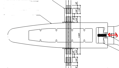
The steel rod assembly below is used to brace this Egg like looking vertical aluminum member for the purpose of stress reduction.
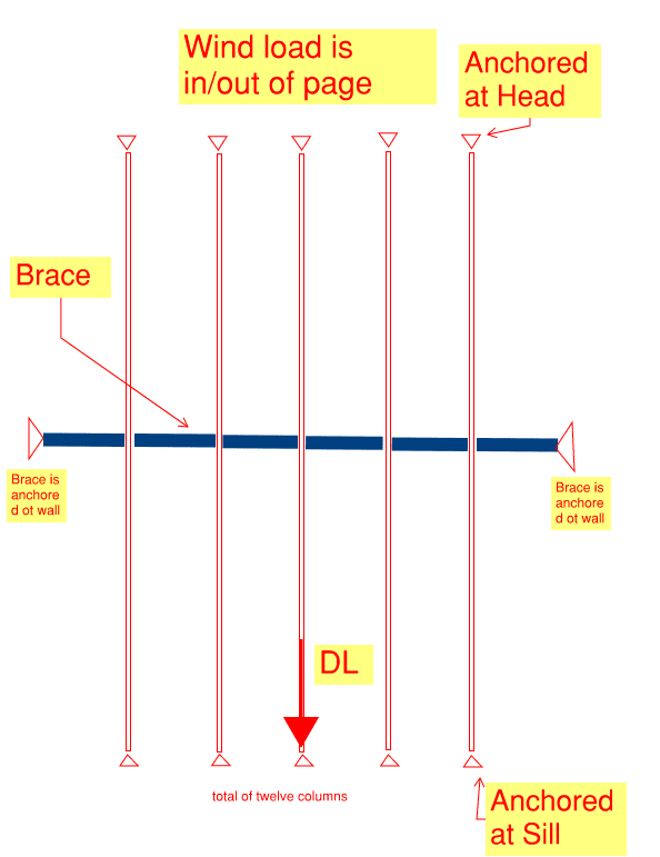
This vertical member is subject to wind load (red arrow) and axial ( dead load into the page transferred to ground) only.
There are 12 such columns at 5 ft on center. All braced with the same rod assembly below.

1- Any issues or concerns with rod being used as a brace?

2- What is the load on the brace?

3- Do you consider this aluminum member a beam, a column, or a beam column?

4- Does the rod need to be anchored to the wall on each side or not?

Screenshot_2023-02-24_145937_wora8a.png


Screenshot_2023-02-24_154935_v0mbyp.png
 
Replies continue below

Recommended for you

1. Were does the brace force go? what is the load path to ground or some other element that resists the cumulative brace forces?
2. Try looking into AISC Appendix 6 - Stability Bracing for Columns and Beams (see if the Aluminum Design manual has a similar section)
3. Everything is technically a Beam-Column
4. If the brace does not have a complete load path to the foundation then it effectively does nothing. (this is an oversimplification without getting into the weeds of buckling analysis)
 
1davek said:
1- Any issues or concerns with rod being used as a brace?

Is the intent of the bracing to restrain weak axis buckling alone? What's your plan for torsional bracing? Horizontal mullions? The glass (not technically allowed any more but still common).

1davek said:
2- What is the load on the brace?

That depends on your answer to my question above. Either way, be sure to account for the accumulated bracing demand across all of the members being braced.

1davek said:
3- Do you consider this aluminum member a beam, a column, or a beam column?

In many applications like this the member will be predominantly a beam. But, yeah, if the thing is tall and glass is being supported a mid-height levels, some beam-column consideration may be warranted.

1davek said:
4- Does the rod need to be anchored to the wall on each side or not?

If the rod can resist compression in addition to tension, without buckling, then you could anchor the rod on only one side. Otherwise, the brace is a tension only member and you'd need to anchor it on both sides such that the brace would be able to go into tension for both directions of mullion buckling.

 
@ KootK

The purpose of the brace is to reduce unbraced length and therefore Lateral Torsional Buckling. Not using the glass and there are no horizontals. Local buckling on the mullion have been checked.
The braces bolts/nuts on the rod are torqued and are in full tension.
I asked whether this is primarily a column or a beam as the process of determining the load on the brace in Appendix 6 for beams and columns are different and result in considerably different values.
The rod is anchored on either end to the walls.
The rod and the connection to the walls have been sized for total load on brace ( brace load on one column times the number of bays (6)).
There are no horizontals.
 
1davek said:
The purpose of the brace is to reduce unbraced length and therefore Lateral Torsional Buckling

There are usually multiple effective lengths pertaining to multiple possible modes of buckling. So it's not necessarily a given that, just because you say that you mean to reduce the unbraced length, you are targeting LTB.

With respect to LTB bracing, one wouldn't normally use rod bracing for that because rods will struggle to provide the flexural stiffness required to torsionally brace the mullions. Regardless, the numbers will be your guide.

1davek said:
I asked whether this is primarily a column or a beam as the process of determining the load on the brace in Appendix 6 for beams and columns are different and result in considerably different values.

Based on what you've told us thus far, I suspect that you want the beam values.

1davek said:
The rod is anchored on either end to the walls.

If this is really torsional LTB bracing, you don't need to anchor it to either wall.


@Kootk

Thank you for your informative replies.

Target is LTB for sure.

The beam section of the Appendix has requirements for the compression flanges of the beam to be restrained. Column section does not have such requirement. Other consultants on my field use Column section. Unfortunately the appendix does not cover Beam-Columns.

Whether I use the beam or column values the numbers work. The only hiccup is that compression flange brace I indicated above. What is your opinion on that? The tension in the rod prevent rotation of the mullion?

 
Hi gents,

Great to see really interesting and in-depth discussion here. Adding my two cents.

1- Any issues or concerns with rod being used as a brace?

I do not perceive any issue with rod being used as bracing element (e.g., buckling restraint) provided the overall effect and design capacity of the restraint are assessed proportional to the anticipated structural behaviour and forces it will be subjected to and shall have sufficient stiffness and strength to control movement at the brace locations. This approach has been successfully implemented for the 3 Times Square NYC façade as an example (albeit for glass fin mullion). It would also be prudent to consider the installation constraints, which is keeping the alignment between the rod (I would think you are using stainless steel) and aluminum mullion.

2- What is the load on the brace?

The load on the brace shall consider the beam-column condition.

3- Do you consider this aluminum member a beam, a column, or a beam column?

The aluminum member is considered beam-column, as it is subject to both axial compression (due to self-weight / glass weight – though these loads will not be significant compared to if it is a primary column member) and bending (due to transverse load, i.e., wind).

4- Does the rod need to be anchored to the wall on each side or not?

It can be designed for both conditions. However, you may want to avoid asymmetric load distribution, which anchoring on each side of the wall would be the preferred option.


I assume you have already considered the effective minor axis radius of gyration (rye) in your calculation to improve the lateral buckling capacity and appropriately used the +/- 0.5 term to account for the effect of the load direction?

For example, a simple span beam with a gravity load hung from the bottom flange (for which +0.5 is used - load acts away from the shear center) will sustain a higher bending moment than the same beam with the load applied to the top (compression) flange (for which -0.5 is used - load acts toward the shear center).

 
Status
Not open for further replies.
Back
Top