Continue to Site

Eng-Tips is the largest engineering community on the Internet

Intelligent Work Forums for Engineering Professionals

  • Congratulations KootK on being selected by the Eng-Tips community for having the most helpful posts in the forums last week. Way to Go!

Load Path of Frames w/Braces at Every Other Story

Status
Not open for further replies.

CN-EIT

Structural
Feb 10, 2020
31
Take the following two braced frames analyzed for a lateral load in one direction at each story:
Frame 1:
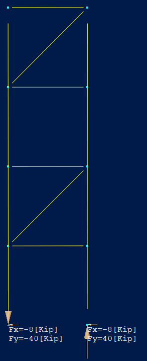
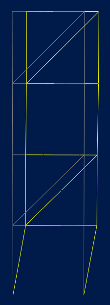
4 - 10'-0" stories, diagonal brace at stories 2 & 4
Frame 2:
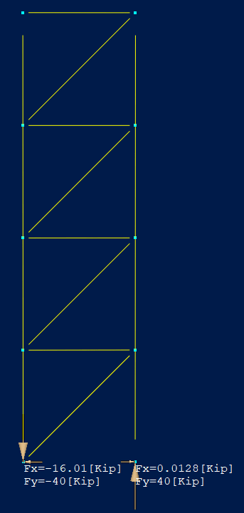
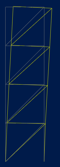
4 - 10'-0" stories, diagonal brace at all stories

Looking at frame 2, I am able to verify the brace forces using the method of sections. Once the bracing is no longer present at each level (i.e. Frame 1) the brace forces jump dramatically and brace forces calculated per method of sections are no longer are accurate. Intuitively that makes sense to me however mathematically I can not understand it. I may not fully understand the criteria wherein the method of sections is applicable, though I assume that by removing the brace at stories 1 & 3 the columns act as rigid links between braced stories and experience bending/shear and not a strictly tension/compression force which is why the brace forces increase as much as they do.

Could anyone provide any insight as to the mechanics I am observing but not understanding or a reference that would prove beneficial?
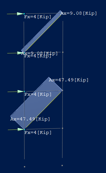
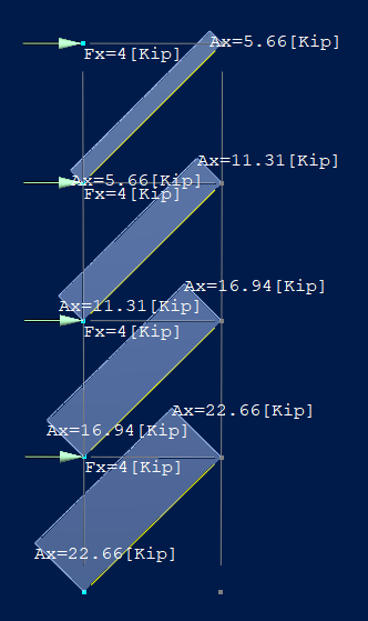
Frame_1_ipveyz.png

Frame_2_ikxc9o.png


Thank you,
 
Replies continue below

Recommended for you

I don't see how frame 1 can be stable. How does it react lateral load between GL and 1 ? bending in the vertical posts ?

In frame 2, why is Ax > Fx ? shear in the vertical posts ? 0.83kN in both ?? In frame 2 overall, 16 kN applied, diagonal react 22.66kN, so shear in verticals = 3.33kN (opposing Ax, summing with Fx).

another day in paradise, or is paradise one day closer ?
 
Fascinating. Could you post:

1) the base reaction for both frames and;

2) the deflected shapes of both frames?
 
rb1957:
I am not sure in plane stability would be compromised in frame 1. I think you are correct that where the bracing is omitted, the beams act as struts and the lateral load is resolved into shear and bending in the column. As for Ax and Fx in frame two: Fx is the lateral load being applied to the frame and Ax is the axial load in the brace.

KootK:
See below.

Frame 1:
Frame_1_-_Reactions_lprsev.png
Frame_1_-_Deformed_vueaqj.png


Frame 2:
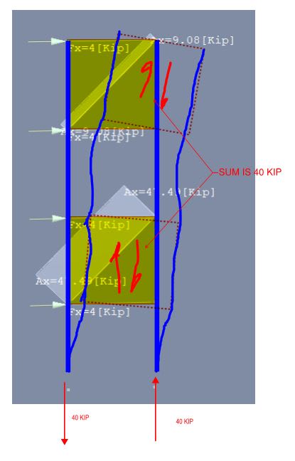
Frame_2_-_Reactions_uz5hqe.png
Frame_2_-_Deformed_j73pio.png
 
Your assumption is correct, that in the first case the columns are taking shear and bending. Consider the node on the right of the third story: it has no means of reacting the horizontal load imparted by the beam except by shear in the column. That's likely why the method of sections isn't working out, because the truss assumption of only axial load is invalid here. I'd check out a statics book for their treatment of trusses, like Hibbeler's "Engineering Mechanics, Statics". Also it's nice to see someone else using RAM!
 
For the deflection plots, can you make it plot accurately between the nodes so that we can see what's going on?
 
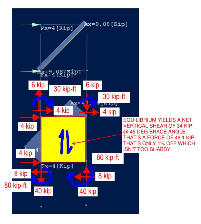
You will notice that, for both frames, the summation of the brace forces is identical at 56.6 kips. That's because, in both cases, the same vertical shear must be resisted by the braces: 40 kip worth.

As far as your ability to hand check the statics goes, I think that your best bet would be to view this frame as an odd version of two stacked moment frames. You might be able to ballpark your numbers by hand using a moment frame approximation method like the portal frame method etc.

C01_yzzjrn.jpg
 
HS PA EIT:
I took a look through my old Hibbeler Statics & Structural analysis books. Neither were outright conclusive however after reading a bit I am starting to think about static determinacy and whether or not that is the better explanation for the method of sections not yielding results that correspond to the model.

KootK:
Sorry, thats all Ive got for deflected shape though I could provide nodal displacements if that would help you.
 
Perhaps this will speak to you. I got all of the numbers by way of portal frame and equilibrium and got reasonably close.

C01_c8qqk9.jpg
 
As the columns are continuous you’re effectively getting part Vierendeel action over the unbraced storeys.
 
- did you model hinges at the beam and brace ends?

- to get a better deflected shape add a bunch of dummy reporting nodes, really to get better pDelta results you should segment the columns into multiple pieces per lift and manually define the unbraced lengths for the design checks.

Let’s see the shear and moment plots also please.


My Personal Open Source Structural Applications:

Open Source Structural GitHub Group:
 
KootK:
I appreciate your equilibrium analysis. I am have limited experience with portal frames but I can follow satisfying the equilibrium. That being said (and speaking to my initial confusion with analysis) I believe that the frames are statically indeterminate and while frame 2 can be analyzed by sections, frame 1 would require the stiffness method analysis (in part because of the point that MIStructE IRE brought up about Vierendeel action).

Celt83:
The beams and braces are all hinged with the bases of the columns pinned.
 
CN-EIT said:
..I believe that the frames are statically indeterminate..

Yup, but as you can see, I used the portal frame method to address that and was able to nail the brace force within 1% just doing back of envelope stuff. No stiffness method. If your question here is really just "is this system indeterminate" then, yeah, it is. Both setups are indeterminate with the impact being less when all of the stories are concentrically braced. On the other hand, if your question is how to use approximate methods to verify computer output and truly understand the mechanics, see my stuff.
 
Let's try it like this.

CN-EIT said:
I may not fully understand the criteria wherein the method of sections is applicable

For your example in this thread, the method of sections is not applicable because equilibrium is affected by those blue moments shown in my sketch below, which is why I showed them. Once you obtain those moments via the portal frame method, the direct stiffness method, the flexibility method, virtual work, or a dozen other possibilities, you're off to the races.

C01_phbsjx.jpg
 
KootK:

You answered each of my questions quite succinctly; though, I seem to have failed to properly or clearly ask said questions. Thank you for that. I have only briefly read about the multitude of analysis methods you mentioned but I'll admit I do not understand any of them in great depth. Looks like I'll be starting with the Portal Frame method since it seems like engineering without understanding the mechanics is more alike to a best guess.
 
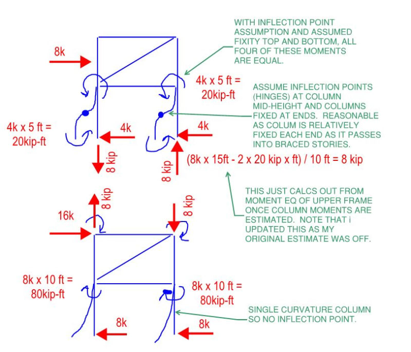
You're most welcome CN-EIT. With dinner, a glass of wine, and a Vikings episode between my last post and now, I can see that I was a little over excited about this. It was fun as I was initially stumped by your results too and very much enjoyed sorting it out in my own mind.

As for the portal method, it's basically as shown below for the two faux moment frames. You just assume reasonable inflection points based on the expected deflected shape, call those hinges, and carry forward with the statics on what have been reduced to determinate frames.

In a way, the supposed simplicity of approximate methods is over rated. For non-trivial situations, you often have to have an understanding of the behavior in your head before you can apply the method fruitfully. So it's cart before horse a bit in that respect.

C01_vlwr69.jpg
 
Ah…, a soft story at the ground floor level, and then every other floor. That’s a nifty new structural concept.

 
Yeah I came to post the same thing dhengr, but you beat me to it.... Classic soft storey.

 
With regard to seismic:

1) Always a good thing to have an awareness off.

2) This may well just be an exercise of intellectual exploration regarding behavior, exclusive of seismic concerns.

3) I think that OP's in North Dakota so there's a very real possibility that he or she is not losing much sleep over seismic.

4) Having a soft story at every other floor is actually much better than having it at only one floor. In fact, if one were to do this over a twenty story building, I think it fair to say that the soft story problem would effectively go away. That, because the setup would encourage inelastic behavior in a uniform-ish fashion all the way up the building and the twenty story building would effectively become ten stories of oddly proportioned moment frames. Obviously, this wouldn't match up with any of the US prequalified moment frames and the braces would have to be designed to yield etc. And there's higher modes of vibration to consider and all that jazz...
 
KootK,

You are correct, the region this building falls in is not seismically controlled (whew!). The question I posed is indeed an intellectual exploration. I am reviewing a previous design of a building which is 4 approximately equal stories with a foot print of 25'-0" x 10'-0" x 32ft tall. It is steel framed with inset CFS studs and 2"x12 gauge strap x-bracing welded to columns at stories 2 & 4 on all four sides. This lateral force resisting system is what I needed to better understand since it would seem that the braces were originally quite undersized for the forces they would experience.
 
Status
Not open for further replies.

Part and Inventory Search

Sponsor