Continue to Site

Eng-Tips is the largest engineering community on the Internet

Intelligent Work Forums for Engineering Professionals

  • Congratulations KootK on being selected by the Eng-Tips community for having the most helpful posts in the forums last week. Way to Go!

load path?

Status
Not open for further replies.

n3jc

Civil/Environmental
Nov 7, 2016
187
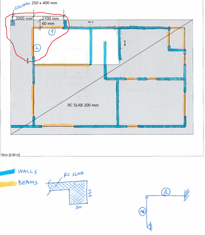
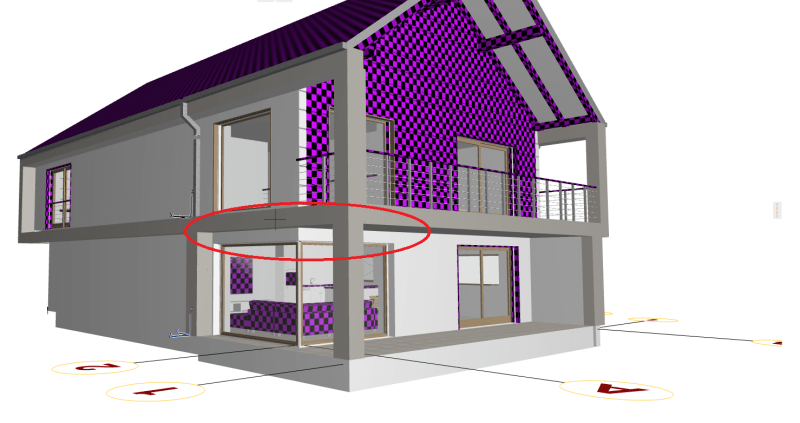
Residental building, corner beams in the ground floor.
Slab 200 mm thick.

WHat is the load path in your opinion:
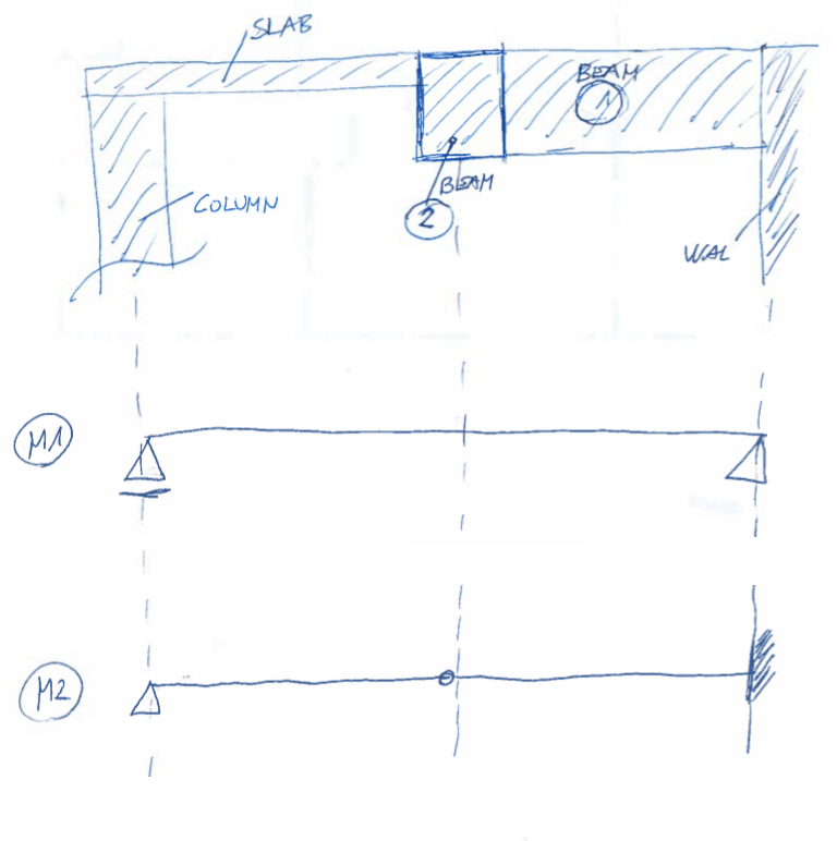
model M1 - acting more as simple span beam (600 x 200 mm)
model M2 - acting as cantilever beams that supports slab

I would say its closer to model M2 because its stiffer. But I get a lot reinforcement in the bottom of 600 mm wide part of the slab in my FEM software.
I'd love to see some opinions.


GROUND FLOOR:
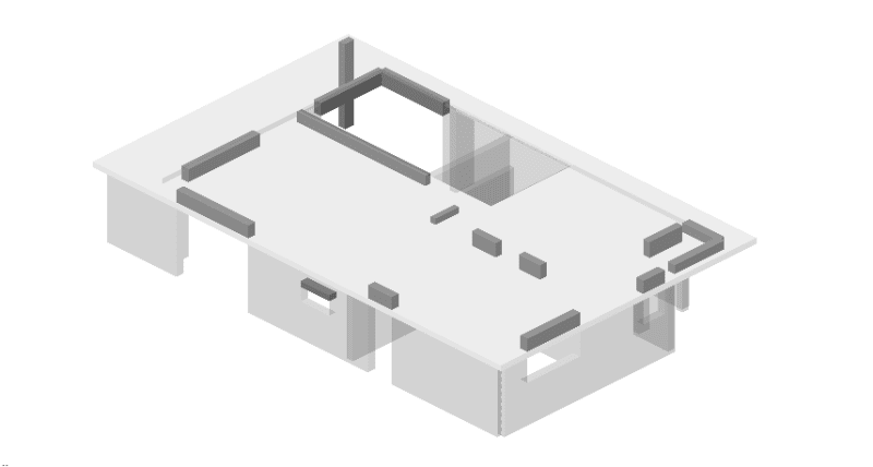
3d_vse_uq8ux8.png


2d_fvafvz.png


3d_gowv1z.png


laod_path_mbe80o.png
 
Replies continue below

Recommended for you

To get any real continuity the detailing would probably be horrific, and I wouldn't trust a residential contractor to pull it off, so I'll vote for 2. But that's here in the Eastern US where if you use anything but 2x4's the contractor has a fit.
 
In situations such as yours, the stiffer beam will try to act as a cantilever and less stiffer beam will try to rest on the more stiffer beam. Anyhow there will be maximum displacement at the free end of cantilever.
In your model, if the slab is not free to move at corner column then it will be trying to restrain the displacement of cantilever beam. This may be the reason why you are seeing positive bending moment at 600 wide part of slab.
Also, for a 2.7 m length, i don't think the beam depth you are providing is stiff enough to be acting like a cantilever at its full potential.

Euphoria is when you learn something new.
 
1) The fact that your slab is drawing large moments may in fact indicate that your beams are not actually stiff enough to attract load as you wish. That said, your FEM may not account for cracking etc which would massively decrease slab stiffness.

2) Even if the slab draws significant load, redistribution should be possible here. I'd take a look at the beams assuming no help from the slabs and estimate deflection at the cantilevered end. Unless that value is very small, I'd pack the surrounding slab with top and bottom reinforcement to limit crack widths.

3) I do prefer your model M2 for the primary, intended load path. Among other things, it can be detailed to resist shear with stirrups rather than just bare concrete.

4) Even if you go with M2, I would calculate an upper bound load that the slab strip path would attract and use that for your punching shear check at the corner column. The punching shear resistance at the column is bound to be brittle in nature and not capable of the same redistribution that the slab will be.

5) Those cantilevered beams actually back-span over top of the supporting walls a meaningful distance, right?
 
Hmmm...good call on the backspan, KootK. Didn't catch that in the 3D view. Doesn't look like it.
 
Intuitively, I don't like the idea of the exterior deck being relied upon to support the walls and roof above. Also, there doesn't appear to be any thermal break between the exterior deck and interior.

Just spit-balling: I might start the design by assuming the exterior deck didn't provide any structural support for the building (the deck is just a load). Design the interior slab, walls, beams and columns to support the building. Then add the exterior deck and see how the loads redistribute. Design the deck without reducing the capacity of the originally designed members.

Do architects have classes on how to frustrate and challenge engineers with tortured load paths?
 
No - it just comes naturally to the "good" ones.
 
Thank you for feedback.

Yes Kootk, there is a significant backspan for cantilevered beams. I havent put this in 3d model yet.
Cantilevered beams are also 300 / 540 mm instead of 300/440 mm.


Do architects have classes on how to frustrate and challenge engineers with tortured load paths?

Sometimes I wonder if I would be able to come up with something like that on purpose:) Im not sure... but they do it without trying often enough :)
 
From your 3d view, is there a glass wall below the cantilever beams? And is the cantilever supporting a wall load close to its free end?

Even if you're providing a backspan for the cantilever beam, a cantilever of almost 9 ft gives me a funny feeling in my stomach.
If I were you, I will be very concerned about the displacements at the free end of that cantilever.


Euphoria is when you learn something new.
 
Do architects have classes on how to frustrate and challenge engineers with tortured load paths?
Hahaha, I'm glad I've never had the privilege of working with annoying architects then. I've always worked on industrial buildings with mostly agreeable mechanical suppliers. I'm spoiled in the sense that I always provide a load path of my own choosing.

Euphoria is when you learn something new.
 
This will probably not work with dimensions you have available. I would insist on a steel column in the window corner (behind the window). There will probably be significant window frame, so my logic is that slender steel column will not bother anyone. But I'm not an architect, what do I know...
 
kootk said:
5) Those cantilevered beams actually back-span over top of the supporting walls a meaningful distance, right?
The more I'm thinking about this, the more I'm getting convinced that even if a backspan is provided, it will not help the cantilever much. Because wall is a rigid element and what backspans basically do is that they reduce the displacement at cantilever end by displacing it in the opposite direction.

Euphoria is when you learn something new.
 
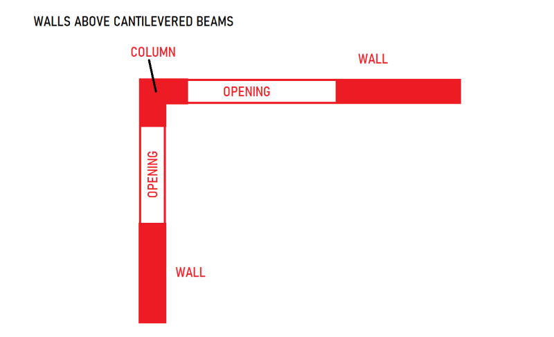
From your 3d view, is there a glass wall below the cantilever beams?

yes, which means that deflections of cantilevered beam should be kept at minimum...


And is the cantilever supporting a wall load close to its free end?

it would be hard to make it worse - right at the end of cantilevered beams there is a column of above floor (see 1st attached image in OP)

G_dl2fmh.png
 
Status
Not open for further replies.

Part and Inventory Search

Sponsor