Eng-Tips is the largest engineering community on the Internet

Intelligent Work Forums for Engineering Professionals

loads due to applying torque to the nut of a threaded bar in the middle of a simply supported beam 2

Status
Not open for further replies.

jedstress

Aerospace
Jan 12, 2011
36
0
0
GB
Hello,

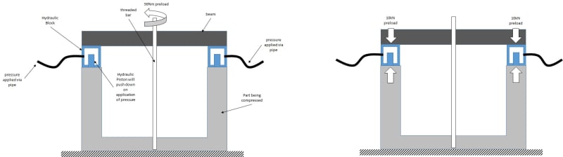
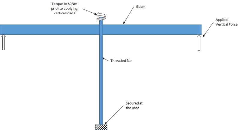
I am currently working on a fixture which is essentially a beam with upward forces being applied at both its ends. The centre of the beam reacts the total load via a threaded bar which is grounded at its base. The previous derivative of the fixture required that the threaded bar be torqued to 50Nm prior to applying the external vertical forces.

The previous calculations did not account for this additional load due to the pretorque of 50Nm. Should it have been included and if so then should the classical lead screw method be used to evaluate the additional force due to 50Nm? And is it simply a matter of adding the external fore and the torque force to get the actual total load in the system? Please refer to the sketch to elaborate on the setup.

Thank you.

setup_xuchnd.jpg
 
Replies continue below

Recommended for you

The initial load from the 50Nm torque won't get added to the applied load - it just starts the loading at some value greater than zero. Once you torque the threaded rod, the ends of your beam will have to provide opposing forces (at the locations where your external load is applied). If you didn't pretension the rod, you'd eventually get to the same load condition, but you would have to take up some slack in the system before reaching your pretension value.
 
Yes, if the bolt gapped from load zero (ie no preload) the the load in the bolt is the applied load. With preload, the joint gaps at some load higher than zero; after the joint gaps the bolt load is the applied load. The simplistic bolt loading diagram assumes the bolt load is equal to the preload up to gapping, and then equals the applied load. The "right" bolt loading diagram increases the load in the bolt slightly above preload (due to joint stiffness) so that the joint gaps at some load above preload.

So the key question to the answer is "does the joint gap under load ?". If it does then to a reasonable extent bolt preload isn't a part of the bolt load. If it doesn't then preload is part of the bolt load.

another day in paradise, or is paradise one day closer ?
 
Hi Canpro,

Firstly thanks a lot for the swift response.
I believe that I have not clearly explained the setup. The external load application points are essentially interfacing with a hydraulics system. Thus first the bar will be pretorqued to its designated values of 50Nm. The resulting load due to the torque is reacted at the hydraulics interface point. Then the hydraulic system applies the external force.

The hydraulic interface is actually a hydraulic cylinder placed between the bottom face of the beam and another component which we are trying to push down. So I thought that the beam would firstly react the load due to torque via vertical reaction at the hydraulic interface. Then the external applied load will be introduced to the setup and hence add to the pre-existing interface loads. I am seeing it as two free body diagrams of a simply supported beam for two load sources. Thus, the accumulative effect would be the combination of the two?
 
Hi rb1957,

Please have a read of my response to CANPRO and let me know if you agree with it.

And would you treat the threaded bar setup as a clamped joint? Doesn't that theory strictly apply to a joint i.e. two mating surfaces?
 
oh, ok … the rod is threaded and the torque is mainly intended to seat the beam.

As you torque the nut you are stretching (preloading) the bolt. And the reaction to this is carried by the beam (in normal joints it'd be compression in the joint faces).
Thus there is some bending in the beam before loading adds more.

Sounds like you were on the right track.

another day in paradise, or is paradise one day closer ?
 
I suppose you could think of it as two load cases superimposed. But try to picture what is happening physically - you're creating relative movement between your hydraulic jacks and the threaded rod - whether it is the rod being tensioned or the jacks moving, you're creating the same effect...and the beam doesn't know the difference. You could conceivably just use the threaded rod to induce the entire load.

To put it another way - If you have load cells between the beam and the hydraulic cylinders, you can predict the load reading based just on the deflection of the beam. Whether that deflection is induced by the rod (pretension) or the hydraulic cylinders (additional applied load) makes no difference to the beam or the load cells.
 
rb1957, would you use the typical preload equation of T=F*K*D to evaluate the preload? I wasn't so sure because it isn't your typical joint where the mating surfaces are in compression.

If I was to use the above equation for an M12 coarse thread bar, I get a preload value of approximately 21kN (k=0.2) and this seems to be far higher than the actual total hydraulic load of 9kN (4.5kN per beam end). Thus, I cant really see why such a high torque value is required for this particular setup. Would you agree that the preload is not doing much in this instance?
 
hi canpro,

I am not 100% sure if I follow you when you say 'But try to picture what is happening physically'. From your recent post it seems like you agree with me adding the pretorque load and the external applied load to get the total load in the system. Correct?
 
Any equation relating torque to tension for a bolt will be a gross approximation in most cases, since several factors are involved. Mostly, the variability has to do with friction, which can vary widely. I'm not at all surprised that it's off by a factor of more than 2. Presumably, in the equation, the "K" value is accounting for the torque applied to overcome friction. Unsurprisingly (as least to me), it's way off. Obviously, your actual "K" value is closer to 0.5. Wax or grease the threads and bearing faces and the K value will drop, but if you have accurate loading from the hydraulics, just use that.

Edit: We went through the whole torque vs. tension thing recently in this thread.
 
Hi HotRod10,

Just a clarification that the 50Nm torque is not actually the required force but it has been stated in the instruction manual as part of setting up the assembly. So I guess it just seats the beam. The actual applied load is via the hydraulic interface which in turn pushes down on a circular ring. Thus the objective of the fixture is to actually push down on this ring via the hydraulic force. Therefore, the threaded rod is not actually applying the intended force but merely reacting the load in the beam as a result.

So my main question was to understand if the 50Nm preload needs to be added to the actual hydraulic load to get the total load in the setup. And based upon the other comments, I believe that it is the case.

And following from that question, I was trying to understand the application of the typical preload equation in scenarios where the joint is actually not a compression joint but two plates a certain distance apart i.e. the preload is dependant upon the bending stiffness of the plates, as opposed to the compression/bearing stiffness? My initial thoughts are that the resulting preload will be less than an equivalent compression joint. Or, have I misunderstood the equation T=F*k*D; is it simply implying that torque = friction x force x distance and has nothing to do with the nature of the joint?
 
I don't think I'm clear on your question regarding how the preload is applied. To me, it seems that the application and magnitude of preload becomes irrelevant once the applied load to the threaded rod exceeds the preload magnitude. The preload applies force to both ends of the beam, so that becomes the beginning point for the jack load applied. Preload or no preload, the hydraulic load is the only load applied. If you preload the system, there is a hydraulic load from that.

Anyway, my comments were regarding the torque - tension relationship. The applied torque is split between adding tension and overcoming friction. Since the normal force on the thread and bearing interfaces changes with the tension applied, for a given coefficient of friction, both components resisting the torque are related to tension. The K value is a 'fudge factor' of sorts that is included to approximate the effect of friction. The thread I linked to goes into much more detail. At the end, we got off onto methods for directing measuring bolt tension, but the earlier posts should be very helpful if you want to understand this better.
 
Hotrod10,I will try to use an example to better explain what I think is happening and by all means correct me where you disagree please.

Torque applied = 50Nm = assumed 20kN.
Reaction at each beam end (hydraulic interface) = 10kN.
External hydraulic force applied at each end = 9kN.
Therefore total reaction at each beam end = 10+9=19kN.
And total reaction at threaded rod = 19x2 = 38kN.

Apologies if I'm dragging this but I thought it would be easier to explain what I am thinking via a numerical example. Otherwise we could misunderstand each others theoretical explanations.

Thanks once again.
 
If by "external" hydraulic force, you mean a hydraulic force in addition to the hydraulic force needed to counteract the 10kN already applied to the jack, then yes, that would be correct. The total hydraulic force applied at the end(s) of the beam is 19kN. Applying 9kN to a jack with 10kN already bearing on it, won't do anything. The 10kN applied to the hydraulics by preloading should show up as a pressure on the hydraulics, unless there's some blocking, etc. that supports that load. If the blocking supports the load, then the hydraulics will have to exert more than 10kN before the beam will move.
 
jedstress, apologies for the confusing post earlier. All I meant was, in addition to superimposing forces, just try to visualize what is happening to this beam during loading. I find this helpful sometimes...I forget about the numbers for a minute, and I let a little video of the loading play in my imagination - I might look a little spaced out at my desk doing this sometimes, but I find it very helpful. When I do this for your problem, it boils down to the relative displacement between the threaded rod location and the supporting jacks - doesn't matter what drives that relative displacement (threaded rod or jack) the result in the beam is the same.

 
Thank you everyone for the responses I have received so far.

HotRod10, after drawing the following sketch of my setup, I can make sense of what you were talking about earlier.
The hydraulic block region essentially behaves like a clamped joint where the 10kN preload due to the 50Nm torque needs to be overcome by the applied pressure in order for any further load to be exerted. Therefore, unless the applied pressure can overcome the 10kN preload then the structure only sees the preload. However, once the pressure overcomes the 10kN preload then the system only sees the applied pressure load. To summarise, the maximum load is the maximum of the preload and the applied pressure. Would you agree with my understanding?
setup2_dhkqov.jpg
 
canpro, it seems like the more I look into it the more confused I get. However, based upon my interpretation of hotrod10s explanation, would you agree with my last post?
 
Hotrod10, the preload is applied on the casing of the hydraulic cylinder. Thus the pressure gauge will show zero pressure in the presence of only the preload due to the recessed design of the piston and load transfer via surface abutment. Hope that answers your question.
 
Yes, that is what I needed to know.

So, when the preload is applied, the casing will be in compression and support the load. As the pressure in the hydraulic cylinder is increased, the preload force will be transferred from the casing to fluid pressure in the hydraulic cylinder. When the pressure multiplied by the area of the cylinder reaches 10kN (assuming the casing to be rigid), the casing will be unloaded, and the hydraulic cylinder is carrying the 10kN. If the pressure increases, the pistons of the jacks go up, the beam bends, the threaded rod stretches, and the forces on the jacks and the rod increase. Once the beam is lifted off the casing, the force at the jacks is equal to the pressure multiplied by the cylinder cross-sectional area, regardless of the magnitude of the preload.
 
Status
Not open for further replies.
Back
Top