Continue to Site

Eng-Tips is the largest engineering community on the Internet

Intelligent Work Forums for Engineering Professionals

  • Congratulations pierreick on being selected by the Eng-Tips community for having the most helpful posts in the forums last week. Way to Go!

Local Buckling vs. Global Buckling 5

Status
Not open for further replies.

MegaStructures

Structural
Sep 26, 2019
376
This thread is not for a specific project, but just a theoretical conversation.

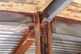
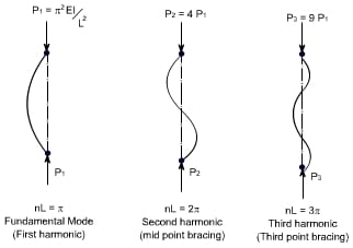
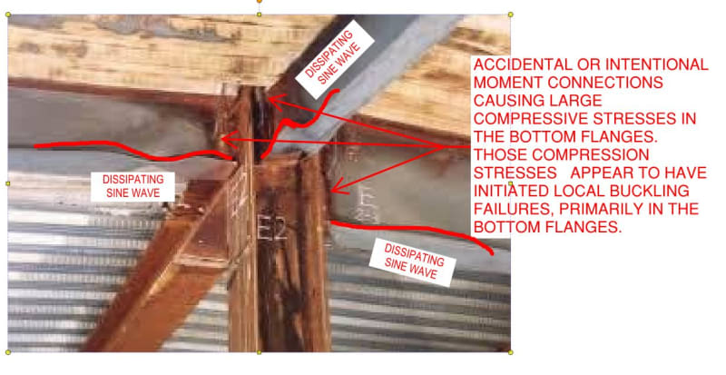
I am trying to better understand the behavior of local buckling in slender elements vs. global buckling in slender columns. I have recently seen a WT brace that is pinned-pinned at its ends and the web appears to be locally buckled (or damaged by construction) near one of the ends, roughly 18" from the gusset plate on a 30' member. I am wondering if it makes sense that this could be a local buckling failure, or if local buckling of the web would occur at midpoint of the member, where the web is the most flexible.

Does the stiffened edge of the plate change the mode shape to something that could buckle at the end, rather than the classic pinned-pinned mode shape with n=1? I don't have a picture of the brace I saw, but I do have another example of local buckling at the end of a member below.

Local_Buckling_rmqpwf.jpg

buckling_mode_shapes_ofrj7e.jpg
 
Replies continue below

Recommended for you

KootK said:
I had thought that we were talking about a simple span, uniformly loaded flexural member

I see the confusion. The member I was looking at was a brace, so I was assuming no bending. I understand the original point now though

KootK said:
This is especially interesting with respect to the programming of FEM elements as it means that, at sufficiently levels of axial load in the system, some members go from being restrained at their ends to being, effectively, pinned at their ends. Tell me that isn't cool?

I've seen this handled in RISA by reducing the MOE to a very small number, but I don't recall ever seeing the member ends behaving differently. Interesting!

KootK said:
Uhh... it becomes difficult to discuss this stuff with any precision without having a very specific case in mind with which to focus the discussion. Does the sketch below help at all? I hope so.

Yes! This explanation resonates very well with me and unless I am interpreting some answers here further explains some of the answers others have given on this post. Local buckling of a WT web in compression cannot be predicted to be in a single location repeatedly due to the mode shape and location of stiffeners. I suppose it is possible (but not always true) that the highest amplitude of the lowest energy mode may occur near the ends of the member and could explain the effect I saw. I'm not real concerned with this particular brace and what happened to it, but I found it to be a very good opportunity to dig into some theory and get a deeper understanding of buckling behavior.

 
KootK said:
A read of that and you'll be heads and tails above most engineers' understanding of local buckling phenomenon.

Purchased!

KootK said:
that said, we're happy to keep helping you with this in the here and now for as long as you continue to have questions and feel as though we're offering value.

I'm very early in my career, actually still completing a postgrad degree while working, but find that I gain a ton of practical knowledge in this forum that it's hard to get from classes/textbooks. Plus I just love talking about engineering.
 
MegaStructures said:
Your claim that local buckling will occur towards the end is because torsional forces may be higher at the end and combine with compressive forces, yes?
My scenario. The LTB occurs in the beam in a half sine wave of the bottom flange. The bottom flange deflect the furthers and it moves the furthest in the centre. So you could argue that the LTB occurs in the middle of the beam. The beam twists but because it is long it twists with no or minimal plastic deformation in the centre.

However the beam is restrained from twisting at the end by its connection. This results in significant torsional stress near the connection which is relieve by plastic deformation.

But of course you've only posted one picture and that isn't even the picture of the failure you saw.
 
MegaStructures said:
Purchased!

KootK = Power Influencer! Chajes owes me a kickback if he's still above grade.

MegaStructures said:
...but find that I gain a ton of practical knowledge in this forum that it's hard to get from classes/textbooks.

Like anything, what you get out of this forum will be commensurate with what you put into it. I've learned far more here than I ever did in grad school and that goes for the theoretical as well as the practical. Grad school is great but grad school professors are usually either teaching material not related to their specialty or material that is only a cursory overview of what their specialty is. That's all that you can really get done in a semester.

You'll find that truly well educated structural engineers have mostly educated themselves, and done so primarily by cutting their teeth in debates with their peers.
 
For what it's worth, when I look at your initial photo, sans-additional research, that looks like classic, bottom flange local buckling per the sketch below.

Having done some power Googling, I know realize that your photo was taken from fire testing. Same answer though as i would see things proceeding like this:

1) Heat reduces stiffness of beams at midspan such that negative moments at connections are exacerbated.

2) Exacerbated negative moments at connections produces large bottom flange compression stresses at connections.

3) Large bottom flange compression stresses at connections produces local bottom flange buckling adjacent to connections.

So the same answer, just with a very particular cause. The bottom flanges may also have buckled prematurely as a result of the heat reducing their stiffnesses locally.

C01_u9rv9l.jpg
 
Looks like the same building. A full scale fire test...well, that explains it!

image_by37hj.png


BA
 
[hairpull]

Thanks Kookt. I had found numerous references to this photo and similar in many postings and presentations. Though very few of them acknowledged that the photo was a fire test. That indeed changes everything!
 
MegaStructures said:
I've seen this handled in RISA by reducing the MOE to a very small number, but I don't recall ever seeing the member ends behaving differently. Interesting!

This will be handled automatically, and internally, when the user directs RISA to consider P-Delta effects. You can find out more about this by looking up Geometric Stiffness Matrix in this excellent book which is also a freebie: Link

C01_xnptpa.jpg
 
human909 said:
Thanks Kookt. I had found numerous references to this photo and similar in many postings and presentations. Though very few of them acknowledged that the photo was a fire test. That indeed changes everything!

You're welcome. Context... tough to do without.
 
Those examples are local bucking (including web buckling).

Local buckling occurs where local buckling stresses are critical. In a prismatic section this will be where the bending force is maxim.
 
Status
Not open for further replies.

Part and Inventory Search

Sponsor