Eng-Tips is the largest engineering community on the Internet

Intelligent Work Forums for Engineering Professionals

Local failure assessment of nozzle junctions - weld sharp edges 1

Status
Not open for further replies.

fem.fan

Mechanical
Jun 7, 2021
33
0
0
AR
Hi, i need to analyze the nozzle junction of a pressure vessel (designed by ASME XIII div. 1) according to appendix 46 (following the steps of div. 2 part 5).
i am using an elastic plastic model.

i´ve searched a lot of threads of this subject but none of them answers my particular inquiry:

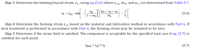
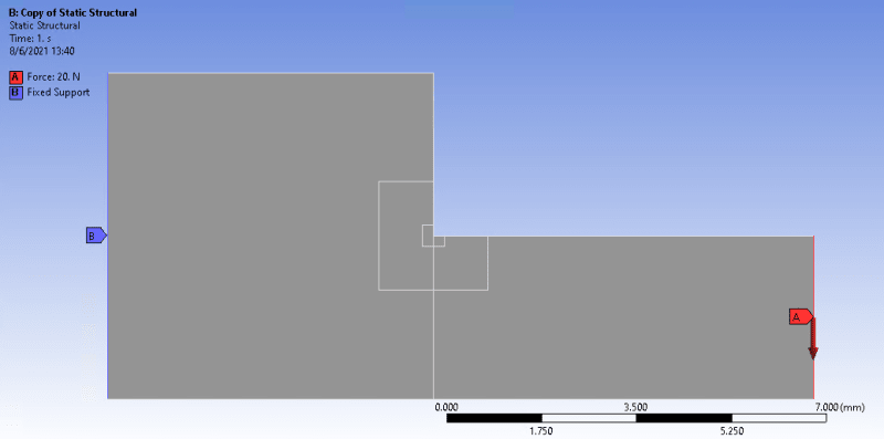
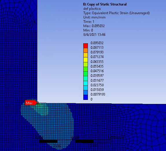
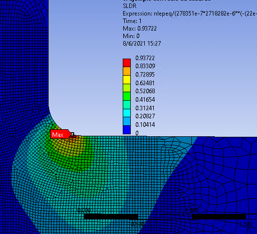
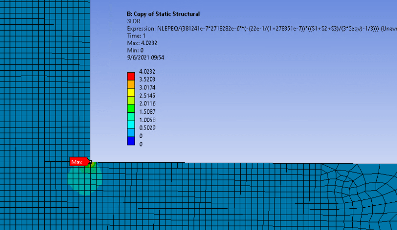
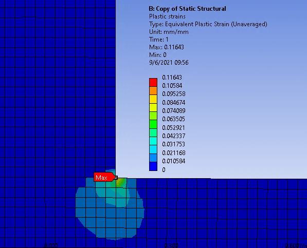
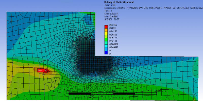
when modeling the welds with sharp edges, there is a stress singularity and of course the stress and strains do not converge to a value when refining the mesh. even though for plastic collapse failure mode it is possible to ignore this effect, when analyzing local failure it is problematic, as there will always be large and unrelistic plastic strains that surpass the allowable by the code.
it is not possible to model a fillet radius since it is not known, besides of producing a huge computational cost.

the following image ilustrates the situation.
singularity_l9xiwv.png


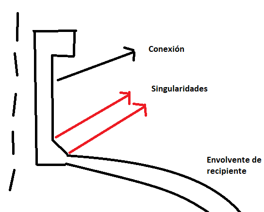
how can i verify this failure mode in this contion?

thanks in advance
 
Replies continue below

Recommended for you

The methods for dealing with stress singularities are:
- add fillet
- include plasticity
- ignore it and read results from different location
In this case you considered all these approaches. But keep in mind that the analysis with plasticity included is not unrealistic as in real life notches like that will also cause large stress concentrations and local yielding. But usually this yielding is limited to really small area and doesn’t indicate failure.

There are also special methods for weld assessment designed to bypass stress singularities. These approaches include hot-spot stress method and structural stress method. They are very useful when determining fatigue life of the weld.
 
FEA way, thanks for your reply.

Perhaps i was not clear enough, but what i mean is that according to paragraph 5.3.3.1 (see image) the local failure criteria must be met for all points in the model, this includes de weld edges.

local_failure_upzrzd.png


Since the plastic strains near the edge are too high, this criterion will never be met there.
 
if you model the weld as a chamfer with linear material, then yes you'll see an "issue". the quotes are there 'cause it isn't a real issue, but we won't tilt that windmill today.

if you model the weld as a (circular) fillet (rad) then even with linear material I doubt you'll see an "issue".

if you model with non-linear material and a chamfer then you'll see highly localised yielding at the weld transition (kink).

"at every point" is something that'd be written in a textbook. "at every significant point" is more real, but opens the discussion to "what's significant ?"

another day in paradise, or is paradise one day closer ?
 
TGS4 as i can see from the abstract, that paper talks about how to compute the strain limit in the nodes being that the finite element results are given at the gauss points. but my question has to do with the singularities that arise from modeling welds with sharp edges.
 
if you want to look at that detail (the very edge of the weld, then why model it in a manner that'll give the worst possible result ?

Would you model as a weld sitting on top of the plate, 2 solid elements ... a brick and a wedge, or would the weld material be essentially part of the plate, 1 solid element ... a tapering brick ?

another day in paradise, or is paradise one day closer ?
 
fem.fan - trust me, it's the same issue.

Plus, at your "singularity" point, one of the principal stresses is zero, so your triaxiality is low.

How are you calculating your limiting plastic stain, or better yet, how are you calculating your SLDR (strain limit damage ratio)?
 
TGS4 - i am defining a "user defined result" in ansys with the formula provided by the code (i uploaded an image in a previous post). The program calculates the SLDR at each gauss point. Then i can extrapolate the results to the nodes.
i´m not sure if this answers your question
 
At least you are following a preferred method.

From the paper:
Conclusions
A mesh that appears to be sufficiently converged for both stresses and strains may not necessarily be so for SLDR. In general, a much higher mesh density is required for determining SLDR. This effect may be even more pronounced around discontinuities.

However, provided that the mesh density was sufficiently high, the Ductile Damage Material Property and Calculate at the Gauss Points and Extrapolate methods produced similar results. The Calculate at the Nodes and Interpolate method was the outlier. Accordingly, the Ductile Damage Material Property and Calculate at the Gauss Points and Extrapolate methods are both considered suitable implementations of SLDR.

The best method to test whether or not the mesh density is sufficient appears to be to compare the averaged and un-averaged results. Special attention should be paid to the un-averaged results to determine if the SLDR results appear highly discontinuous or not. Furthermore, if the value of SLDR is negative while plotting the un-averaged SLDR, this too would indicate that the mesh is insufficient. More rigorous test methods may be available, but this simple check appears to suffice.
So, are you following the advice recommended in the final paragraph I quoted above?
 
Let me explain with a simple example. I have run several simulations of a simple 2D model to avoid the large computational costs of modeling the nozzle for "investigation purposes". The following is an image of said model:

Captura_lertay.png


the following images shows the Plastic strain and the SLDR respectively:

Plastic strain (zoom in the zone of interest)
Captura_xjdddi.png


SLDR
Captura_sktjif.png


As you can see, there is a zone with SLDR values greater than 1. So i modeled a 0.1 and 0.2 mm raidus but still the SLDR was greater than 1 there. Only with a 0.3 mm radius the SLDR was greater than 1 at each point.

My conclusion is that, when analyzing local failure, modeling the fillet radius is a must, otherwise you can´t be sure that he criteria is satisfied near the weld edges.
 
when you say "plastic strains", are you modelling non-linear material ?

Nice idea, modelling simple examples. Have you tried different angles ?
For example, how about adding a chamfer to the corner (to simulate the weld).

How are you modelling the non-homogenous nature of the weld ... the parent material, the heat affected zone, the weld material ??

What's "SDLR" ?

This is the impracticality of "at every point". Every structure has always had details beyond yield. Only they are highly localised and had viable loadpaths around them and so do not hazard the safety of the structure; unless it fatigues.

another day in paradise, or is paradise one day closer ?
 
rb1957 - a non-linear material, taken from ASME Section VIII, Division 2, Annex 3-D would be the curve.

SLDR is a term that I invented, called the Strain Limit Damage Ratio, which is the ratio of the calculated equivalent plastic strain divided by the limiting plastic strain, as described in Equation 5.6 of ASME Section VIII, Division 2, Part 5 (and shown above in one of fem.fan's posts.

This relates to a very specific failure mode where, under certain stress states (high triaxiality), the material behaviour transitions from ductile (and represented by the elastic-plastic stress-strain curve) to be more brittle (the limiting plastic strain decreases). It needs to be assessed everywhere, because brittle fractures can occur spontaneously with only one application of a load. I'd be happy to discuss the failure mode in greater detail, if you would like. It's rather fascinating.
 
Cuurently i am using a bilinear curve (first line to yield stress and second line from yield to UTS) due to licencing limitations. (we plan to upgrade de licence for commercial cases to be able to use a multilinear model of the ASME curve).
the material is SA-516 Gr. 70

αsl = 2.2
m2= 0.2784

FYI, the following image shows the SLDR of the exat same model with the only difference of a 0.3 mm radius.

Captura_gi2had.png
 
Your uniaxial strain limit is too low by a factor of 10.

Is your 2D model really 14mm x 7mm with a 7mm x 3.5mm chunk cut out? And a 20N force?

Details, please.
 
The big square is 6mm x 6mm the rectangle is 6mm x 3 mm. thickness 1mm.

The uniaxial strain limit is 0.381. Why do you say it´s too low? i computed it from table 5.7
the force is 80 N (i changed it because i also changed the yield strength that i had reduced for testing purposes).

updated results:

SLDR
Captura_f8k5ax.png


Plastic strains
Captura_une2mi.png


Strain limit:
Captura_kxlmqk.png
 
Now i see what you mean, i´ve corrected the value of uniaxial limit strain and the SLDR is below 1 everywhere. thanks for the correction. However, don´t you consider that generally speaking one needs to model the radius? otherwise, the strains results there are not real at all.
 
Status
Not open for further replies.
Back
Top