Continue to Site

Eng-Tips is the largest engineering community on the Internet

Intelligent Work Forums for Engineering Professionals

  • Congratulations KootK on being selected by the Eng-Tips community for having the most helpful posts in the forums last week. Way to Go!

Locally Embeded Steel Sections Inside Concrete Columns (Design) 1

Status
Not open for further replies.

MAB70

Structural
Aug 19, 2019
25
Hi Everyone,

I have a reinforced concrete tower that requires locally a cantilever mezzanine in one of the floors.

We had to propose the mezzanine to be in steel for its light weight and additional strength.

To get rid of the complicated connection of anchors to concrete columns we are proposing to have locally embeded steel sections into the concrete columns so we can connect steel to steel for the mezzanine beams structure.

Does anyone have any guidance/reference on how to calculate the embedment depth for the steel section and studs inside the concrete to safely transfer the expected moments?

Any other alternatives are welcome.

Capture_dmx1l5.png
 
Replies continue below

Recommended for you

Speaking solely from the analytical part of the question:
1. Calculate the maximum expected moment at the concrete face based on the load from the cantilever steel floor
1a. Size the steel floor beams
2. Determine if the concrete can resist the moment
3. Determine the strength of available shear stud connectors
4. Create an analytical model based on the rotational capacity of the studs and the moment arm between them

I stop there because that is where the sketch has too many questions to answer.
-It appears you have a 4:1:3 ratio between column width, cantilever length, and out-to-out of the studs shown
-It appears you have all W sections
-It does not show the magnitude of the load nor the magnitude of the scale
-It is unclear how you would insert or form this and where it's located on the tower

As far as other ideas:
1. Use an HSS column
1a. Use an HSS column with a through plate knife connection that extends beyond the face of the column
 
Other ideas: castin plates for formwork and welded bolt sockets.

"Programming today is a race between software engineers striving to build bigger and better idiot-proof programs, and the Universe trying to produce bigger and better idiots. So far, the Universe is winning."
 
I think there is more that need to be considered here than embedded depth and no. Of studs.
Obviously, the worst case scenario will be when only one cantilever is loaded.
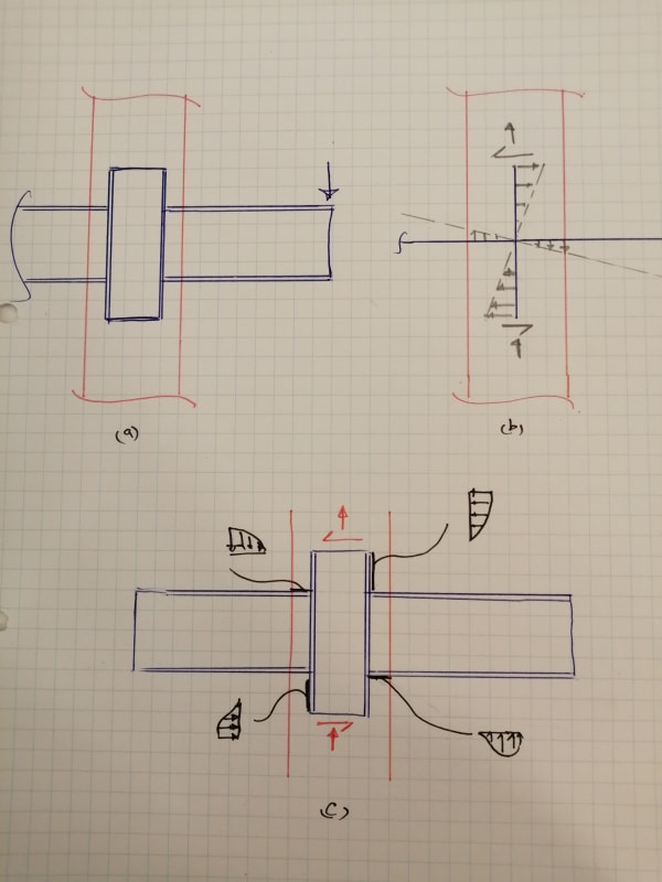
Considering the local behaviour, the most critical case will be for the rigid rotation of the steel beam-column, as shown in fig b. This rotation will produce stresses in the sorrounding concrete as shown in fig c. You must make sure your column is also designed for these local stresses.
IMG_20200217_171125_xtiqc2.jpg

You can search the web for the design of embedded column in foundation for bending moment. Behaviour will be somewhat similar.

Also, if span and loads permit, why don't you design a connection for a continuous beam passing through the Rcc column instead. Analyis, in this case, will be less complex than for your proposed detail.


Euphoria is when you learn something new.
 
I think I have a reference for this.....but before I dig it out....I want to be sure here: you are purposing embedding those "Cantilever Steel Floor/UB Steel Beams" into this concrete column without any embedded plate correct? You just need the length of beam to be embedded to transfer these forces right?

 
@Blackstar123, Thats exactly what i need to check but couldnt find any reference to do the actual math and checks.

Do you have any reference even for the embeded column in foundation example? (There are areas one side cantilevers also)

@WARose, Yes thats what i believe would be more robust connection, the steel beams will be either welded to the columns, i need any reference to do the local concrete checks.

 
My thoughts:

1) In my market, embedding the beam like that would be very unpopular with contractors because of the disruption to the column formwork.

2) Unless the steel sections are small, and the column large, I worry that the embedded pieces may cause concrete consolidation issues.

3) I've only seen the vertical member embedded solution used where the primary load being transferred was axial. Where bending moments predominate, I don't love the scheme because your mechanisms of resistance encourage lateral spalling of the column concrete. The health of the column surely trumps the health of the mezzanine. For this reason, if you go with the embedded steel scheme, I'd prefer one that relies on the formation of vertical force couples rather than horizontal.

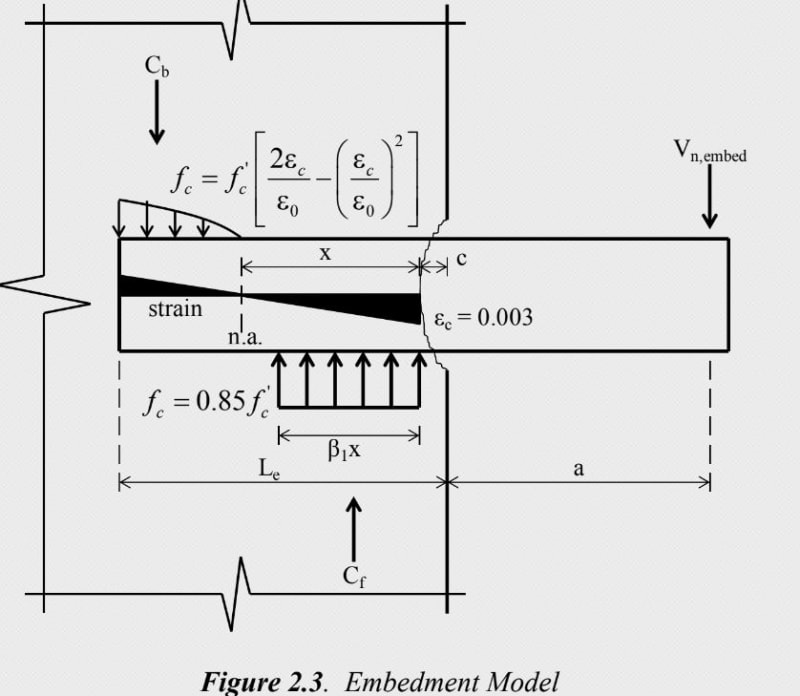
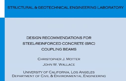
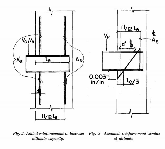
4) As for design recommendations, I would be inclined to look at steel coupling beams in concrete shear wall assemblies. Lots of research effort has gone into that area recently and you'll find no shortage of applicable design guidance. The snippet below is taken from one such design guide.

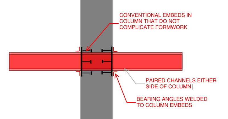
5) If it were me, and field welding was acceptable, I'd do something like I've shown in the first sketch below. It's simple, it does't mess with your column formwork, and it doesn't risk column concrete consolidation problems. Best of all, it provides a robust mechanism for moment resistance that exploits vertical force couple resistance and maximizes the distance between those forces.

c01_irrdwf.jpg


c02_d9bmrc.jpg


c03_cpal7t.jpg
 
@WARose, Yes thats what i believe would be more robust connection, the steel beams will be either welded to the columns, i need any reference to do the local concrete checks.

Ok. The reference I would recommend is 'Composite Construction Design For Buildings' by: Viest, et al. (1997; published by: McGraw-Hill/ASCE). Chapter 6 deals with connections (including composite to non-composite). I don't see a type quite like you have.....but they do take on a steel beam (transferring forces) passing straight through a concrete column. At another point (p. 6.86-6.89) they take on the design of a "coupling beam" (i.e. a cantilever steel beam from a reinforced concrete wall). They figure the required embedment length of this beam using methods & stress distributions similar to what Kootk shows above.

Hope this helps.
 
ASCE published a report on this: ASCE Task Committee (1994). “Guidelines for design of joints between steel beams and reinforced concrete columns,” Journal of Struc. Engrg., ASCE, Vol.120, No.8, pp. 2330-2357.
 
OP said:
Thats exactly what i need to check but couldnt find any reference to do the actual math and checks.

I have never provided this kind of detail, so I can't really refer a good source for deep reading. I just wanted to make sure that you are also conscious of the stresses developing in surrounding concrete. But I'll be reading the document KootK has referred for sure. I completely agree with every point he has summarized.

Euphoria is when you learn something new.
 
@KootK, as usual you always add much value and thoughts to this community, thank you very much for your help. I think i will go with that solution for the continuous cantilever at both ends. I have found same example in PCI hand book so would be great to compare results.

@WARose,Blackstar123 Thanks !!
 
@Mahmoud: Thanks for the kind words. Happy to help. If you're going with the PCI method, this article may be of interest: Link. I believe that it was one of the source documents for that procedure.

c01_sir7fz.jpg
 
You can also google cazaly hanger for more info like Koot mentions.
 
Thank you for giving us closure. So few OP do this.[pipe]

Euphoria is when you learn something new.
 
Status
Not open for further replies.

Part and Inventory Search

Sponsor