Continue to Site

Eng-Tips is the largest engineering community on the Internet

Intelligent Work Forums for Engineering Professionals

  • Congratulations waross on being selected by the Eng-Tips community for having the most helpful posts in the forums last week. Way to Go!

Location of expansion tank and circulator relative to the plate heat exchanger

Status
Not open for further replies.

kikonas68

Mechanical
Feb 13, 2024
16
Hello.
Which one of these arrangements is more correct than others regarding the location of circulators in both circuits?
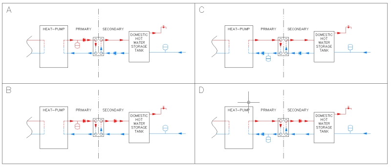
HPE_vumgi3.png
 
Replies continue below

Recommended for you

I am sure that they do in fact size the expansion tank for the possibility of filling up the solar collectors with steam. Wouldn't you? Only need to account for the volume in the collectors. Can't be more than a few gallons of volume in the collectors for a typical domestic system.

Caleffi seems to be showing the expansion tank on the pump discharge side in the cases where there is an intervening stop valve on the collector return. Guaranteeing the expansion tank is in communication with the collector sounds like a pretty good reason to me.

Openminded curiosity, logic, and physics ("Why is this successful international hydronics company doing it differently than usual?") are more useful tools than dogmatism ("Expansion tanks must be on the pump suction. This successful international hydronics company is doing it wrong").
 
Actually you are right about the expansion volume. I think the rule for sizing of expansion tanks in solar systems is to do regular sizing plus the collector volume. That only applies if the collector is above the tank. But that still doesn't resolve the location.

Open mindedness =/= parroting what you read somewhere without questioning and understanding why. Companies make mistakes or weird decisions. World-wide leaders in the car industry decided to put the gas tank right in front of the rear bumper and all the Pintos went up in flames during a crash. Larger and profitable company =/= always makes good decisions.
And as you see above, the very same company also shows the expansion tank on the pump suction side.

Every solar system has a check valve to prevent thermo-siphoning. Some pumps have it built in. So that doesn't explain why they show it 2 different ways. The above picture also has a check valve shown despite the expansion tank being on pump suction side.

If there is a valid reason to put the tank on the discharge side for solar system, I will be the first one to do that. But so far we haven't learned what the reason is and why it should be better than the suction side. If I planned to use the Caleffi solar station, I would contact them and inquire. I'm sure they have an answer. I have experienced that I contacted companies with questions like that and they admitted to being wrong in their documentation. Trust, but verify.
 
About Caleffi both editions in question(no3 and no6 of idronics series) are dated back to 2008-2009. Maybe things have been reconsidered since then?
In addition the current link for the data sheet of solar expansion vessels (including sizing):
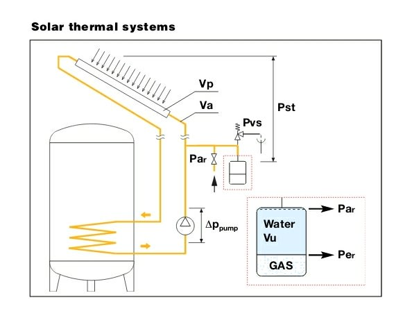
where tank is downstream of pump
IMG_20240222_015250_j276x7.jpg


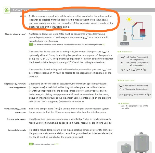
I also think we have the answer 🙂 from Reflex:
IMG_20240222_020147_kaqzr4.jpg

In this case let's note that in order to avoid cavitation the head of the pump is also added to determine po(so is said I think inside the data sheet-sizing from Caleffi).
 
Maybe this is their way to prevent home owners from fooling around with valves and causing damage. Like if the storage tank has isolation valves or pumps have isolation valves.
this isn't really an issue in professional settings. Boiler shave isolation valves, but the expansion tank is not on boiler side of the valves.

What they should do to be save is add a relief valve between collector and any valve. This may be legally required.

You have to remember, the solar industry is full of (well meaning) hobbyists. So they have to dumb it down a bit. The damage of the expansion tank on the wrong side is less than the damage of a home owner closing off valves. a LOT of the material published is targeting DIY people, not professionals. a LOT of the documents violate many local plumbing and mechanical codes.
 
Thank you.
HVAC-Novice said:
What they should do to be save is add a relief valve between collector and any valve. This may be legally required.
Right (it is also stated in "HYDRONIC HEATING AND COOLING" (ASHRAE Handbook Systems and Equipment)).
 
Status
Not open for further replies.

Part and Inventory Search

Sponsor