Continue to Site

Eng-Tips is the largest engineering community on the Internet

Intelligent Work Forums for Engineering Professionals

  • Congratulations KootK on being selected by the Eng-Tips community for having the most helpful posts in the forums last week. Way to Go!

Log Headers/Beams

Status
Not open for further replies.

JeffCastillo

Structural
Apr 10, 2021
8
Hello:

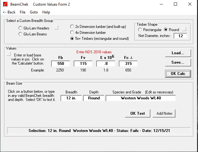
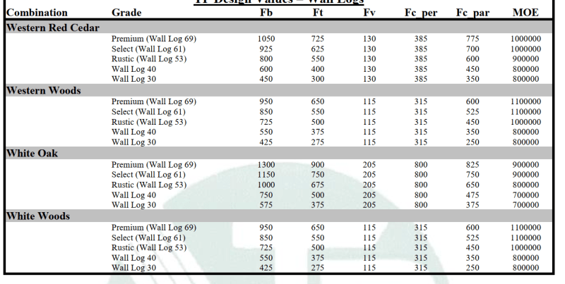
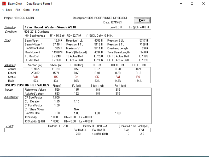
I am engineering a log cabin in Utah, 80 design snow load for roof; I am trying to determine how I can calculate for (2-3) Stacked Logs on top of each other to act as a "Header" or "Beam". It is a side ridge for a porch, 12' span and 2' overhang, I am trying to use Western Woods Wall Log 40 and the technical data sheet from Timber Products Inspection May 2020. We are using a program called Beamchek to check if the values inputted passes or fails, but I have no way of inputting stacked courses or anything like that. I am just trying to determine how I can get (2) 12" diameter WW WL 40 to work as I can get a 12" Diameter DF Select to pass, but I have no way of showing the math as to how I can get (2 or 3) Stacked courses to pass and was wondering if anyone could help?

Here is my thought process, I know for beams/headers, we can call out 2 or 3 ply beams that are nailed together and become stronger as their moment of inertia increases, allowing the deflection to become less, and the Section modulus to help with the moment, so if I am thinking correctly, can I treat the Section Modulus for a round log as the courses (so in place of a single 12" diameter, having (2) courses would be 24" diameter), increasing the strength of (2 or 3 stacked logs)?
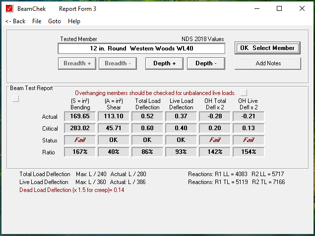
4_hbik3s.png


2_mjmllr.png


3_a6zk6r.png


Capture_psucza.png
 
Replies continue below

Recommended for you

You need to consider shear flow between the logs. That's the horizontal shear that keeps the individual beams acting as one rather than three individual beams. That's the only way to take advantage of the increase in moment of inertia from the increased depth. Otherwise it's just I[sub]x[/sub] x n.
 
For most types of wood connections, fastener slip makes it impractical to attempt to get anything close to full composite behavior out of stacked plies. The good news stemming from that is that it makes the design of the member pretty easy. Ratio your load out to the two stacked plies according to their relative stiffness's (EI). Then just design each of the plies in isolation for that load.

Things get a bit wonky with regard to how shear gets transferred to the support in these situations but I believe that it's common practice to disregard that. If possible, I'd like to see the low beam capable of resisting the total shear in both plies.
 
KootK - ever designed a log cabin? I got to do one last summer; really fun project. This reminds me that I need to reach out to the guy and see if he's started. He told me I was only allowed to inspect his work if I share a cigar and a dram of whiskey after...

I digress. The joinery is pretty neat if done right, and you can get some pretty good interlock. Combine that with some of the specialty log fasteners FastenMaster has developed and I got a warm fuzzy about it - especially when you consider the level of conservatism inherent in wood design.
 
phamENG:

The moment of inertia for a circle is jsut pi/4*Radius^4, so what you are suggesting is to just take my radius, find my moment of inertia and multiply it by the number of courses I want? Moment of inertia is only used to check deflection, am I wrong? I am in the process of designing a spreadsheet for lateral to determine the OlyLog screw spacing required to check "Shear" as seismic is controlling with all that weight. We typically call out 24" Spacing, sometimes tighter if needed, but we try to stick with 24" Spacing for the OlyLog Screws and it has always worked for us. I've engineered quite a few, but if I couldn't get a certain diameter to work, I would just call out for (2) or (3) Full Log Courses over a header as I know that header is not going to fail with those logs, they are heavy and strong...

KootK: How would you ratio your load out to the two stakced piles in accordance to their relative stiffness? I.e I have a distributed load of 850 PLF, Length of 12' with a 2' overhang.

 
phamENG said:
KootK - ever designed a log cabin?

Never, although I've always wanted to and have had some near miss proposals for it. I dug up some of their standards back in the day and found it all very interesting.

phamENG said:
The joinery is pretty neat if done right, and you can get some pretty good interlock. Combine that with some of the specialty log fasteners FastenMaster has developed and I got a warm fuzzy about it - especially when you consider the level of conservatism inherent in wood design.

Show me just what you mean and I'll do my best to show you why I don't feel that it's composite. As far as composite behavior goes, I have little faith in anything other than adhesives and, perhaps, screws installed diagonally such that the horizontal shear would put them in tension.

Conservatism in wood design, in and of itself, does little to enhance composite behavior. It might buy you some fudge room but, then, the difference in stresses and deflections between fully composite and non-composite can be massive.
 
OP said:
KootK: How would you ratio your load out to the two stakced piles in accordance to their relative stiffness? I.e I have a distributed load of 850 PLF, Length of 12' with a 2' overhang.

w1 = wt * EI1 / (EI1 + EI2)

w2 = wt * EI2 / (EI1 + EI2)
 
Jeff - if you don't have composite action between the logs (connections that ensure horizontal shear flow between "plies"), then each log will act as an individual beam and they'll share the load according to their relative stiffness. So, in essence, you have three individual beams carrying the load. If they are connected compositely, then the moment of inertia changes to consider all three logs as a single beam. For simplicity's sake let's consider 3 square timbers. No connection between them and you're 'total' moment of inertia is going to be 3*bd^3/12. If you connect them compositely, you're moment of inertial becomes b(3*d)^3/12. That's an increase of 2.667 over the non-composite section made up of the same members. Moment of inertial, section modulus, stresses, etc....all interconnected. I'm assuming you know that as you are a structural engineer - correct?

KootK - you've been gone too much lately. I'd momentarily forgotten that you call people out on everything....

Composite action here is not a guarantee or easy. If you have a traditional log structure with gaps and clinking...no composite action regardless of the number of fasteners you have. The 'new-fashioned' log homes that come as kits with heavily milled logs and neat interlocking pieces, it's pretty easy. There's lots of surface area for adhesives where you need it.

The one I designed was in between. It was a traditional log cabin, but the logs were cut to interlock along their lengths. I agree that complete composite action isn't a practical expectation in wood and I also agree that the conservative nature of wood design doesn't increase the composite nature of the connections. By fastening them together at relatively short intervals with LogHog screws I felt comfortable checking it as a composite section, though I never pushed it. If I needed the screws at 24" o/c to handle the shear, I'd put them at 8". As long as the structure could support dead loads and a small proportion of the live loads as non-composite, I'm okay looking at 50% to 75% composite action for the full load scenario. I'll take it to 90% with proper adhesives and inspections.


phamENG said:
KootK - you've been gone too much lately. I'd momentarily forgotten that you call people out on everything....

True on both counts. Thanks for the extra info. My concern on this came about from some of the information posted by Agent666 in the past. Apparently Eurocode has a method to evaluate the level of composite action achieved and, in may cases, it's not much and is neutered by relatively small amounts of slip.

phamENG said:
The 'new-fashioned' log homes that come as kits with heavily milled logs and neat interlocking pieces, it's pretty easy. There's lots of surface area for adhesives where you need it.

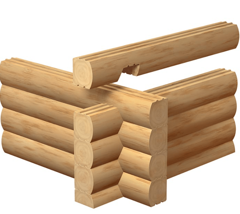
Can you illustrate or describe the interlocking somehow? Hopefully it's not just what's shown below since, in the absence of adhesive, that would almost encourage shear slip. Almost like shear friction in reverse.

c01_u1q0qb.png
 
In those cases adhesive is absolutely required. I'm saying the nature of the interlock is such that you have lots of surface area to achieve the bond. The heavily processed joints make for reliable contact surfaces as opposed to hollowing out the bottom of a log with a curved draw knife.
 
To achieve composite action, you need both a clean and smooth bond surface, if attempting to bond in the field. I would say that neither of those criteria would be met on a typical log home construction site, and as such, I would strongly caution against calculating member strength/stiffness based upon composite action.
 
Status
Not open for further replies.

Part and Inventory Search

Sponsor