I have a part which is intended to sit in a jig that restraints it on all 6 degrees of freedom, with only the necessary and sufficient points. This is required for part function, as it is manufactured on a jig, tweaked on the same jig, QC'd on an identical jig, then installed with another identical jig that ensures it goes into the final assembly with all the functional parts in the right position.
Which sounds like it would therefore be a GD&T home run, except that the degrees of freedom are locked up using, in order of precedence:
1) One vee notch in the part that slides on a shaft in the jig - locks translation on two axes (some error introduced by the fact that a vee is not really a spherical bushing - but it's close for our purposes).
2) One flat face in the part perpendicular to the shaft axis right next to the vee notch, and a matching flat shoulder on the shaft - locks translation on the final axis.
3) One flat face in the part tangent to the aforementioned shaft, which bears against the same shaft, locking up a rotational axis
4) Two datum targets distant from all of this, which lock up the remaining rotational axes.
So, this all works just fine kinematically - there is only one way that this part sits in this jig. Functionally, gravity makes it sit stably in the jig. We can gauge off it. There is some 'crosstalk' between axes since for example the final two datum targets control the final two rotation axes in a mix depending on the errors. But that isn't a problem for us functionally.
But, this seems to fly in the face of the standard, at least implicitly. Though I can't find explicit statements. Issues like:
1) This frame has at least 4, and maybe even 5 datums in each FCF to build the datum reference frame.
2) We are not anywhere close to a 3-2-1 situation, we're more like 2-1-1-1-1 or 3-1-1-1 or something depending on how disingenuous I get with combining not-really-an-axis datum features into axes (A-B) or similar.
To be clear, the positions and types of these datums is not really negotiable, they've been picked for part function quite carefully. So if I can't make this work with GD&T, it's going to be "Write an essay about it" instead, which I would like to avoid.
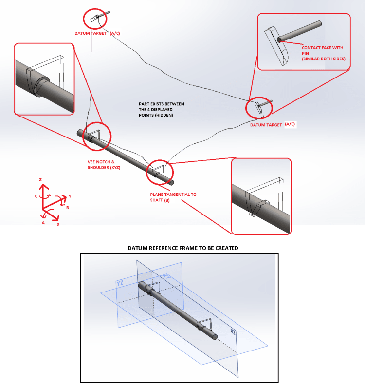
Below is a screenshot of the datum features/simulators of the part/jig to try to make the above more clear, and a set of planes that represent what I want to try to create. I've had to delete the part outside of the jig points for IP reasons. I've left the jig solid and the part transparent for clarity. And I've zoomed in the individual parts where the part sits on the jig also for clarity.

Can you guys see a way to make this work per the standard via GD&T? Is doing so a non-issue? Or is it an unsolvable issue?
Which sounds like it would therefore be a GD&T home run, except that the degrees of freedom are locked up using, in order of precedence:
1) One vee notch in the part that slides on a shaft in the jig - locks translation on two axes (some error introduced by the fact that a vee is not really a spherical bushing - but it's close for our purposes).
2) One flat face in the part perpendicular to the shaft axis right next to the vee notch, and a matching flat shoulder on the shaft - locks translation on the final axis.
3) One flat face in the part tangent to the aforementioned shaft, which bears against the same shaft, locking up a rotational axis
4) Two datum targets distant from all of this, which lock up the remaining rotational axes.
So, this all works just fine kinematically - there is only one way that this part sits in this jig. Functionally, gravity makes it sit stably in the jig. We can gauge off it. There is some 'crosstalk' between axes since for example the final two datum targets control the final two rotation axes in a mix depending on the errors. But that isn't a problem for us functionally.
But, this seems to fly in the face of the standard, at least implicitly. Though I can't find explicit statements. Issues like:
1) This frame has at least 4, and maybe even 5 datums in each FCF to build the datum reference frame.
2) We are not anywhere close to a 3-2-1 situation, we're more like 2-1-1-1-1 or 3-1-1-1 or something depending on how disingenuous I get with combining not-really-an-axis datum features into axes (A-B) or similar.
To be clear, the positions and types of these datums is not really negotiable, they've been picked for part function quite carefully. So if I can't make this work with GD&T, it's going to be "Write an essay about it" instead, which I would like to avoid.
Below is a screenshot of the datum features/simulators of the part/jig to try to make the above more clear, and a set of planes that represent what I want to try to create. I've had to delete the part outside of the jig points for IP reasons. I've left the jig solid and the part transparent for clarity. And I've zoomed in the individual parts where the part sits on the jig also for clarity.

Can you guys see a way to make this work per the standard via GD&T? Is doing so a non-issue? Or is it an unsolvable issue?

