Continue to Site

Eng-Tips is the largest engineering community on the Internet

Intelligent Work Forums for Engineering Professionals

  • Congratulations waross on being selected by the Eng-Tips community for having the most helpful posts in the forums last week. Way to Go!

Longitudinal shear between web and flange of T-beam

Datpt

Structural
Sep 29, 2023
13
Hi everyone,

Recently, I’ve been designing a lot of ribbed slabs and have a question about the calculation of transverse reinforcement for resisting longitudinal shear between the web and the flange of T-beams.

The general approach for this is clear: we use the strut-and-tie model, where transverse reinforcements are in tension.
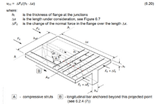
1731931961370.png
However, Eurocode 2 (2002) states that when there is also transverse bending (which I understand as the slab’s bending moment about the beam’s longitudinal axis), the reinforcement should be calculated as follows:

"In the case of combined shear between the flange and the web, and transverse bending, the area of steel should be the greater of that given by Expression (6.21), or half that given by Expression (6.21) plus that required for transverse bending."

Expression (6.21) provides the area of transverse reinforcement needed for longitudinal shear. Based on my understanding, this means we should detail the reinforcement as:
Max(rebar for longitudinal shear,0.5×rebar for longitudinal shear+rebar for transverse bending)

Meanwhile, the 2023 version of Eurocode states:

"If reinforcement is placed only in the tension zone due to transverse bending, the area of steel should be the greater of that required for bending and that required for shear."

This would translate to:
Max(rebar for longitudinal shear,rebar for transverse bending)

On the other hand, the FIB Model Code suggests:

"Unless a more detailed analysis is undertaken, reinforcement for introducing forces into the flanges is to be superimposed on that required for transverse bending."

This implies: rebar for longitudinal shear+rebar for transverse bending

In summary:​

  • Eurocode 2 (2002):
    Max(rebar for longitudinal shear,0.5×rebar for longitudinal shear+rebar for transverse bending)
  • Eurocode (2023):
    Max(rebar for longitudinal shear,rebar for transverse bending)
  • FIB Model Code:
    rebar for longitudinal shear+rebar for transverse bending
I’m a bit confused. Personally, I find the FIB Model Code approach to be the most reasonable. However, I assume the Eurocode has specific reasoning behind not superimposing the reinforcements.

What do you all think about these approaches? I’d greatly appreciate hearing your opinions and insights!
 
Replies continue below

Recommended for you

The top and bottom steel in the slab will not both be active at any one location flexurally. And you can rely on both for the longitudinal shear transfer. I suspect that all three methods really reduce to the same thing considering that. I'd rewrite it as follows:

1) Put half of your longitudinal shear reinforcing in the bottom and half in the top. Obviously, lap splice the bottom.

2) Add the transverse bending top steel to that required by [1].

I feel that you could distribute the longitudinal shear reinforcing anywhere within the section. Whatever you need for transverse bending will be additive to whatever you've used at that same location for longitudinal shear however.
I do agree with that.

Lets call [1] is steel for shear and [2] is the steel for bending.

The one that you rewrite is similar to FIB's model code which said that the rebars should be superimposed. Total rebar is [1]+[2] where [1] can be on bottom or top while [2] should be on the tension fibre (often be the top).

However, Eurocode 2023 told us to take the greater one between [1] and [2]. Many documents such as "How to design according to EC2" suggest that the steel for bending [2] can also compensate for the steel for shear [1]. I am very curious about that.

On the other hand, when the beam is relatively wide (e.x. 1000mm) we often only anchor 10d of slab bottom rebars to the beam web. In that case, the bottom rebar of slab can not be used as a part of [1].
 
In my mind, there are two separate things that might be getting confused in the sources.

A) If you are examining shear friction on a plane through the slab adjacent to the web, then you can use the same top steel for both flexure and the shear friction. Effectively, the flexure compression block becomes the shear friction clamping force.

B) If you are examining load spread out through the flanges laterally, as the sketch that you posted suggests, then that would be additive to the tension face reinforcement.
I agree, they should be added up since both forces cause tension stress on rebars.
Maybe the EC2-2023 has some typos.
 
I have old copy of EC-2 ( EN 1992-1-1:2004 Incorporating corrigendum February 2014) . Although it is not explicitly stated, as far as i understand , clause 6.2.4 Shear between web and flanges is for T-beams cast monolithic with slab . I would like point out the clause (6) If vEd is less than or equal to kfctd no extra reinforcement above that for flexure is required.
For the T-beams monolithic with the slabs spanning between the beams, the reinf. required for transversal bending of the flange caused by the slab between the beams in general very well exceed the reinforcement calculated to resist shear between flange and web.

I did not see EC2-2023 but my gut says , EC2-2023 is reasonable.

My opinion
Well, based on that statement, the transverse bending bars can also be used to resist the longitudinal shears.
However, I cannot imagine the mechanical meaning of that since both forces can occur at the same time and both of them induce tension forces on transverse bars.
 
However, I cannot imagine the mechanical meaning of that since both forces can occur at the same time and both of them induce tension forces on transverse bars.
In addition to hogging reinf. of slab , in general , half of the slab span reinf. extends to support which compression force develops for these bottom reinf.
Can you show a real case where Max(rebar for longitudinal shear,0.5×rebar for longitudinal shear+rebar for transverse bending) or rebar for longitudinal shear+rebar for transverse bending compromising EC-2 (2023 ) ?
 
However, I cannot imagine the mechanical meaning of that since both forces can occur at the same time and both of them induce tension forces on transverse bars.
It could very well be this, what does make sense mechancally.
A) If you are examining shear friction on a plane through the slab adjacent to the web, then you can use the same top steel for both flexure and the shear friction. Effectively, the flexure compression block becomes the shear friction clamping force.
 

Part and Inventory Search

Sponsor