Continue to Site

Eng-Tips is the largest engineering community on the Internet

Intelligent Work Forums for Engineering Professionals

  • Congratulations KootK on being selected by the Eng-Tips community for having the most helpful posts in the forums last week. Way to Go!

Looking For Boeing Design Manual Reference -Frame Analysis 1

Status
Not open for further replies.

edmeister

Member
Jun 25, 2002
97
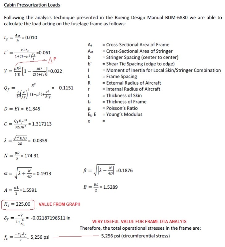
Recently encountered a Boeing Design Manual Reference (BDM6830)... That provides the stress value on a frame given cabin differential pressure & various Frame / Stringer / Skin Material properties & Dimensions. Until - i can evaluate further - it seems an intriguing methodology to be used in DTA analysis for an aircraft where proprietary loads values are unavailable. I worked down the equations realizing that the equations pertain to the axis of some graph (that was not included). Thus without detailed explanation of the calculations nor the graph - its a useless methodology & reference. Has anyone seen or used this methodology?
.. Note: Prior to getting bombarded by Boeing proprietor warnings & "death-treats" by my fellow readers - Yes .. I am aware. But there must be an origin to this methodology that Boeing uses - some paper or report. It segregates pressurized loading of the skin & loading to the frame with inputs from the stiffness of the stringers.
- Any leads would be appreciated. & No .. I do not have access to the BDM - else I would not be asking.
 
Replies continue below

Recommended for you

Could it be NACA Report/Tech Note TN 2612, by W. Flugge, 1952?
 
Reference is close - but seems an early beginning - value from 'mysterious' graph (in my source document) allows calculation of frame deflection and lastly stress in frame flange.
 
Unfortunately, BDM 6830 doesn't have a references section. Also, the general introduction in BDM-6000 doesn't have many references either, apart from FAR 25 and Mil-Hdbk-5.
Try the references in the corresponding chapter of Bruhn. TN2612 is there (that's where I got it).

Another hint... find the corresponding Lockheed Stress Memo, and read Lockheed's references section. If the B's methodology is the same as Lockheed's, those references may apply to the BDM, too. Find Lockheed's frame stress method, read the references, see if the methods match up.
 
Having worked long ago in the Boeing Commercial stress methods group that writes the BDM documents, I suspect the BDM6830 methodology is based on old Boeing internal test data and analysis methods, and you are unlikely to find any public reference data for it.
 
What is the title of BDM6830? Might provide us-all a clue-card...

As I recall [maybe/maybe-not]...

Michael CY Niu was at one-time a Boeing or Douglas engineer, who wrote/self-published a series of [4] excellent design manuals... that might have a glimmer of light.

Also...

Are the design books by Dr. Roskam of any use for 'cross-reference'?

Regards, Wil Taylor
o Trust - But Verify!
o For those who believe, no proof is required; for those who cannot believe, no proof is possible. [variation, Stuart Chase]
o Unfortunately, in science what You 'believe' is irrelevant. ["Orion", HBA forum]
o Only fools and charlatans know everything and understand everything." -Anton Chekhov
 
BDM 6830 Fuselage. (one of the few BDMs I don't have a copy of).

I looked quickly at Niu's books and didn't see anything related to the OP's question.


we've had a HUGE discussion here about stresses in frames from pressure ... everything from "it's fricking critical" to "it's nothing at all".

clearly, in a ideal fuselage, it is restraining the inflation of the skin due to hoop stress, so for some width of skin the frame restricts the radial deflection. And so it is a radial load in the frame (shear in the frame web).

but equally clearly, in a real world frame, with an underfloor beam and maybe a non-circular fuselage then all bets are off and it would probably be better to use FEA.

nice student project ... model it up and test it.

and of course if composites then everything changes ...

"Hoffen wir mal, dass alles gut geht !"
General Paulus, Nov 1942, outside Stalingrad after the launch of Operation Uranus.
 
I attached a section of the analysis - but did not have the graph. Understandably I was very vague with the description - was hoping that it was more common knowledge & easily recognizable .. Does this jar any memories ?
Eng-Tips_dihn04.jpg
 
AFFDL-TR-69-42 STRESS ANALYSIS MANUAL
by GENE E. MADDUX
Air Force Flight Dynamics Laboratory

Chapter 8
8. PRESSURE VESSELS
8.1 INTRODUCTION TO PRESSURE VESSELS
8.2 NOMENCLATURE FOR PRESSURE VESSELS
8.3 THIN PRESSURE VESSELS
8.3.1 SIMPLE THIN PRESSURE VESSELS
8.3.1.1 MEMBRANE STRESSES IN ZIMPLE THIN SHELLS OF REVOLUTION
8.3.101.• MEMBRANE STRESSES IN THIN CYLINDERS
8.3.1.1o2 MEMBRANE STRESSES IN THIN SPHERES
8.3.1.1.3 SAMPLE PROBLEM - MEMbRANE STRESSES IN THIN LYLINDERS AND SPHERES
8.3.01.2 HtADS OF THIN CYLINDRICAL PRESSURE VESSELS
8.3.1.2.1 MEMBRANE STRESSES IN MEADS OF THI1 CYLINDRICAL PRESSURE VESSELS
8.3.1.2.2 DISCONTINUITY STRESSES AT THE jUNCTION OF A THIN CYLINDRICAL PRESSURE VESSEL AND ITS HEAD
8.3.1.2.2.1 INTRODUCTION TO DISCONTINUITY STRESSES
8.3.1.2.2.2 DISCONTINUITY STRESSES AT ;UNCTION OF THIN CYLINDRICAL PRESSURE VESSEL AND HEAD
8.3.I.2,2oZ.I SAMPLE PROBLEM - DISCUNTINUITY FORCES IN CYLINDRICAL PRESSURE VESSELS WITH DISHED HEADS
8.3.1o2.2.3 DISCONTINUITY STRESSES IN THIN CYLINDRICAL PRESSURE VESSELS WITH FLAT HEADS
8.3.1.2.2.3.o SAMPLE PRoBLEM - DISCONTINUITY STRESSES IN PRESSURE VtSSELS WITH FLAT HEADS
8.3o..2o2.4 DUSCONTINUITY STRESSES IN IHIN CYLINDRICAL PRESSURE VESSELS WITH CONICAL HEADS
8.3.1.2o2.4.1 SAMPLE PROBLEM . DISCoNTINUITY STRESSES IN PRESSURE VESSELS WITH CONICAL HEADS
8.3.1.3 BUCKLING uF THIN SIMPLE PRESSURE VESSELS UNDER EXTERNAL PRESSURE
8.3.1.3.1 BUCKLING oF ThIN SIMPLE CYLINDERS UNDER EXTERNAL PRESSURE
8.31•.3.1.1 SAMPLE PROBLEM - BUCKLING oF THIN SIMPLE CYLINDERS UNDER EXTERNAL PRESSURE
8.3.19.32 bUCKLING OF THIN SIMPLE SPHERES UNDER EXTERNAL PRESSURE
8.3.1.4 STRESSES IN SIMPLE CYLIDkRICAL PRESSURE VESSELS DUE TO SUPPORTS
8.3.1o5 CRIPPLING STRESS OF PRESSURIZED AND UNPRESSURIZEC' THIN SIMPLE CYLINDERS
8.3.1.5.1 CRIPPLING STRESS OF SIMPLE THIN CYLINDJLRS IN COMPRESSION
8.3.•1.51.1 CRIPPLING STRESS OF UV"IpKESSURIZED SIMPLE THIN CYLINDERS IN COMPRESSION
8.3.1.5.1.2 CkIPPLING STRESS OF PKLSSURIZEU SIMPLE THIN CYLINDERS IN COMPRESSION
8.3.1.5.2 CRIPPLING STRESS OF SIMPLE THIN CYLINDERS IN BENDING
8.3.1.5o2ol CRIPPLImG STRESS OF UNPNESSURIZED SIMPLE THIN CYLINDERS IN BENDING
8.3.1.5.2.2 CRIPPLING STRESS OF PRESSURIZED SIMPLE THIN CYLINDERS IN BENDING
8.3.1.5.3 CRIPPLIiiG STRESS uF SIMPLE THIN CYLINDERS IN TORS1ON
8.3.1.5.3.1 CRIPPLING STRESS oF UNPMLSSURIZED SIMPLE THIN CYLINDERS IN TORSION
8.3.1,5,3.2 CRIPPLING STRESS OF PRESSURIZED SIMPLE THIN CYLINDERS IN TORSION
8.3.1.5.3.2,1 SAMPLE PROBLEM - CRIPPLING STRESS OF PRESSURIZED SIMPLE THIN CYLINDERS IN TORSION
8.3.1,5,4 INTERACTION FORMULAS FOR THE CRIPPLING OF PRESSURIZED AND UNPRESSURIZED CYLINDERS
8.3.1.5.4.1 SAMPLE PROBLEM . CRIPPLING INTERACTION OF SIMPLE THIN CYLINDERS IN COMPRESSION AND BENDING
8.3.2 STIFFENED THIN PRESSURE VESSELS
8,3.291 THIN CYLINDRICAL PRESSURE VESSELS WITH STRINGERS UNDER INTERNAL PRESSURE
8.3.2.1.1 SAMPLE PROBLEM - THIN CYLINDRICAL PRESSURE VESSELS WITH STRINGERS UNDER INTERNAL PRESSURE
8.3.2o2 THIN CYLINDRICAL PRESSURE VESSELS WITH RINGS UNDER INTERNAL PRESSURE (STRINGERS OPTIONAL)
8.3.2.2.1 SAMPL. PROBLEM - STIFFE14ED THIN CYLINDRICAL PRESSURE VESSEL WITH INTERNAL PRESSURE
8.4 THICK PRESSURE VESSELS
6.4.1 THICK CYLINDRICAL PRESSURE VESSELS
8*4.1.1 THICK CYLINDRICAL PRESSURE VESSELS UNDER INTERNAL PRESSURE ONLY
8.4.1.2 THICK CYLINDRICAL PRESSURE VESSELS UNDER EXTERNAL PRESSURE ONLY
6.4.1.3 SAMPLE PROBLEM - THICK CYLINDRICAL PRESSURE VESSEL
8.4.2 THICK SPHERICAL PRESSURE VESSELS
8.5 ANISOTROPtC PRESSURE VESSELS

Regards, Wil Taylor
o Trust - But Verify!
o For those who believe, no proof is required; for those who cannot believe, no proof is possible. [variation, Stuart Chase]
o Unfortunately, in science what You 'believe' is irrelevant. ["Orion", HBA forum]
o Only fools and charlatans know everything and understand everything." -Anton Chekhov
 
Bingo !
Right on the Money ..
I even had the Maddux Reference in my Library !
Section 8.3.2.2 / formulas identical with what i attached.
Even comes with graphs - but not easy to understand graphs .. OH well.
thx so much.
 
Ed...

My copy of the AFFDL-TR-69-4 [NTIS: AD-759 199] has very clear graphics/charts/tables, throughout. IF You need a 'better/cleaner copy', then search around... or contact me thru ET.

Regards, Wil Taylor
o Trust - But Verify!
o For those who believe, no proof is required; for those who cannot believe, no proof is possible. [variation, Stuart Chase]
o Unfortunately, in science what You 'believe' is irrelevant. ["Orion", HBA forum]
o Only fools and charlatans know everything and understand everything." -Anton Chekhov
 
5 ksi stress in the frames is not negligible.
Especially if that's a nominal stress and limit/ultimate load cases are correspondingly higher.
 
D-amnn ... we can answer just about any question !! ('cept maybe "what was Putin/Trump thinking ?")

"Hoffen wir mal, dass alles gut geht !"
General Paulus, Nov 1942, outside Stalingrad after the launch of Operation Uranus.
 
Hi All

Just to add some relevant information. All of the OEM stress manuals I have seen (Boeing, Grumman, Lockheed, McDonnell Douglas, Curtiss Wright, etc.) including both new and old versions, all reference the NACA series of methods for ring frame analysis. The method depends on the time period the stress manual was published. Later versions of manuals unfortunately no longer provide references in many cases. The NACA series on ring frames in order are: TN-462, TN-929, ARR-L5H23, TN-1219, TN-1310. The most prevalent use are the TN-929 for rigid assumptions and the TN-1310 for flexible frames. Note, actual method for solving the equations is contained in ARR-L5H23. For my own use, we have created both spreadsheet and fortran versions of these to automate the solutions. Note that NACA/NASA did extensive testing to verify these classical methods. OEMs did as well. So, this is considered an industry accepted method.

In addition to the NACA reports, you might be interested in some NASA reports. NASA produced a series of 3 volumes which expanded and documents the numerical solutions in NASA TN-D-401, TN-D-402, and TN-D-403. The solutions are also presented in the NASA Structures Manual (NASA TM-X-73305).

Good luck
 
this would be based on the work from Peenemunde ?

"Hoffen wir mal, dass alles gut geht !"
General Paulus, Nov 1942, outside Stalingrad after the launch of Operation Uranus.
 
Hi rb1957

Not entirely. The efforts on developing methods for ring analyses goes back even before ww2 and spans the globe. Here are some earlier papers (some easier to find than others):
"A Solution of the Circular Ring", by Roy Miller, May 2, 1931;
"Monocoque Fuselage Circular Ring Analysis", BF Ruffner, January 1939;
"Analysis of Circular Rings for Monocoque Fuselages", JA Wise, September 1939;
"Analysis of Fuselage Rings", by Cline and Peery, Curtiss Wright, August 1941;
"Controventamento delle Ordinate Circolari di Una Struttura a Guscio" Dr. Scalamera, June 1940;
"Analysis of Fuselage Rings by the Column Analogy" by D. duPlantier, Consolidated Vultee, April 1944;

Anyways, NACA TN-929, TN-1219, ARR-L5H23 and TN-1310 are the final methods that prevailed and most OEMs incorporated these into their stress manuals by the mid 1950's. There is a Boeing structures orientation manual from 1957 which specifically references NACA TN 929, ARR L5H23 and 1310 as the method for ring frame analysis and even shows examples. Other OEMs also implemented these same methods with the most prevalent being 1310 because it addresses a flexible cylinder and can produce internal loads not only at the frame where the loads are applied but also on adjacent frames. However, the most conservative, is the TN-929 as it assumes a rigid frame.

Just fyi, I believe if you go to the website archive dot org, you will find both the Grumman and Convair structures manuals. The Grumman one sues the NACA TN 929 while the Convair one documents both the rigid 929 as well as the flexible method 1310. By the way, it is unfortunate, but many OEMs are starting to replace these classical industry standard methods which are tried and proven in their manuals with sections on using FEA.

Have a great day
 
"sues" ... watch them fingers ... and no little red line.

funny story. I had a grad adding a report for me. read it over. said it's wrong, check your spelling. what? sigh, you don't spell "assess" "asses". well word didn't pick it up. yes, 'cause it's the plural of "ass".

"Hoffen wir mal, dass alles gut geht !"
General Paulus, Nov 1942, outside Stalingrad after the launch of Operation Uranus.
 
For giggles...

Everyone here knows that E.F. Bruhn Authored 'Analysis and Design of Flight Vehicle Structures' in the mid 1960s... then updated it in the 1970s... Right??

WELLLLL... he also co-authored 'Analysis and Design of Missile Structures' [~1967]!!! This is a fairly short book [relative to ADFVS]... and provides insight in early missile structure-design.

Regards, Wil Taylor
o Trust - But Verify!
o For those who believe, no proof is required; for those who cannot believe, no proof is possible. [variation, Stuart Chase]
o Unfortunately, in science what You 'believe' is irrelevant. ["Orion", HBA forum]
o Only fools and charlatans know everything and understand everything." -Anton Chekhov
 
Status
Not open for further replies.

Part and Inventory Search

Sponsor