Continue to Site

Eng-Tips is the largest engineering community on the Internet

Intelligent Work Forums for Engineering Professionals

  • Congratulations waross on being selected by the Eng-Tips community for having the most helpful posts in the forums last week. Way to Go!

Looking for correct weld symbology 3

Status
Not open for further replies.

blades741

Mechanical
Aug 1, 2012
47
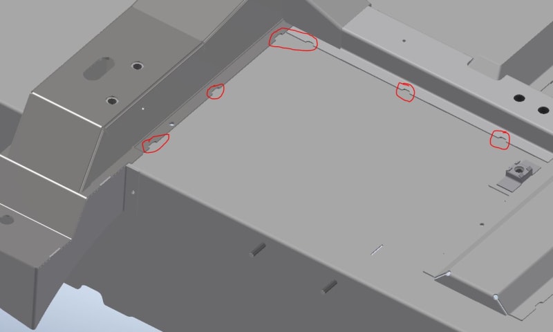
I have a sheet metal welding requirement that does not seem to fit neatly into any of the standard weld type callouts. Typically, the sheet metal being welded together is 16ga. (.060") thick. I've used the fillet weld symbol in the past as a more-or-less generic weld symbol, but obviously this is not a fillet weld in the normal sense, nor is it a seam weld or a plug weld. Being sheet metal, the entire weld location edge of the top part is consumed into the weld. See attached pic for clarification.

Part 2 of this question pertains to spot welds. We either identify weld locations with a rectangular cutout for a stitch weld, or a half-circle for a 'spot' weld (see attached pic). My question here is: is it ONLY correct to call out a 'spot' weld if the parts are welded via. resistance welding, or is it still technically correct if it's an additive weld? All our welds are TIG welds. I really don't want to get bogged-down specifying weld sizes, as the location notches & material thickness drive the actual weld size.
 
 https://files.engineering.com/getfile.aspx?folder=b8c87750-3ce4-454b-b5bd-c81e72cc05e6&file=Weld_Locations.JPG
Replies continue below

Recommended for you

I recommend you get a copy of AWS A2.4 that covers symbols for welding brazing, and nondestructive evaluation.

I didn't find the sketch very helpful is visualizing what you want.

Best regards - Al
 
There aren't off the shelf welding symbols for every conceivable joint. When there isn't, AWS says (paraphrased) that drawings or descriptions other than standard welding symbols can be used. Your drawing looks like you are doing half of a plug and slot weld though.
 
Yes, pretty much as you describe, half plug & half slot. It's a fillet weld in the same manner that a tsunami is a gentle wave, but that's primarily what I have been using. I'm also using spot weld, but that jury is still out (per my 2nd question). Seems like I might need to develop some custom symbols.

 
Do you notch the parts as shown in your attachment ?

Why ?
 
First you need to define the type of joint. Is that a Lap joint ? The picture is a little unclear.
 
@Tmoose: Yes, the sheet metal is notched (either slot or half-round) to identify weld locations.

@capntom62: To your point, it seems like a lap joint, but wouldn't that still require a fillet-weld symbol?

This pic may help show with more clarity. The intended weld location notches are circled, and we are welding 16ga (.060") sheet metal.


Capture_bgnkts.jpg
 
I vote for the lap joint with a fillet weld symbol. While a resistance spot weld makes sense, the numbers may be too few to justify the capital cost of resistance welding equipment.

The base metal is only 0.060-inch thick, so the fillet welds can be no larger from a design standpoint. The length of the fillets should be on the order of four times the size, or no less than 1/4-inch in this case. One should consider the starts and stops of the fillet will likely exhibit some incomplete fusion and underfilled craters. A 1/16-inch fillet size can be challenging to a welder not used to making very small welds. I'm not saying it can't be done, I'm just saying it takes a little practice and good eye sight to deposit them consistently.

The notches in the sheet metal only serve to locate the fillet welds, so calling or considering them to be half plug or half slots is simply incorrect. Depositing the welds using any arc welding process is going to cause serious issues with buckling distortion. Resistance welding would minimize distortion. when added length is needed, ocerlapping spot welds (seam welds) could be used. The current would have to be increased to overcome the shunting effects of initial spot welds. The same strength could be achieved by adding more spot welds spaced slightly to minimize the effects of shunting.

Best regards - Al
 
Thank you Al, that's the simple answer I was looking for (and what I suspected was the case).
Yep, we've seen the issues that can happen with buckling, but that has been addressed with thicker sheet metal in areas, and adjusting weld locations, etc. Of course spot welding would make the most sense here, however the company has not reached production numbers that would support the tooling requirements for spot welding. Getting there, and some sub-assemblies are spot welded. But the requirements for underbody floor welding would necessitate some very huge guns that would only be practical to position with a robot.
 
I've worked with a auto manufacturer in the Detroit area. They use a lot of robots for the floor pans.

Best regards - Al
 
According to ISO standards, this is a fillet weld. This is clearly defined in EN ISO 2553 IIRC.
 
@kingnero, thanks for the affirmation on that.

@gtaw, yep! I worked in bodyweld at Toyota for a few years, so I'm very familiar with how things should be done, or are normally done. Spent some quality time teaching weld robots. I also worked in the greater Detroit area myself for many years, as shops that build the weld equipment & lines.
 
The spot welding depicted on the ESAB website has been around for many years. I used that process while I was working my way through college back in the late 60's. Technically, one would call it an arc spot weld. The system has been tried and true. For limited production runs or when the number of welds simply doesn't justify the capital cost of installing resistance welding equipment, this may be a viable alternative.

Best regards - Al
 
Status
Not open for further replies.

Part and Inventory Search

Sponsor