Continue to Site

Eng-Tips is the largest engineering community on the Internet

Intelligent Work Forums for Engineering Professionals

  • Congratulations pierreick on being selected by the Eng-Tips community for having the most helpful posts in the forums last week. Way to Go!

Looking for Paralleling Generator General Training and Tester Resources

Status
Not open for further replies.

kontiki99

Electrical
Feb 16, 2006
510
I work in an airline Engineering Support Group that supports the aircraft maintenance division. One of our chronic problems involves troubleshooting the electrical system on older 3 engine aircraft. When an aircraft has an odd number of engine driven generators or just a lot of them (as in 747), generators are paralleled on a bus to share the load. Our older aircraft have limited fault reporting ability. I've read that aircraft fault reporting systems probably at best are capable of showing us 20% of the possible faults. The original designers are long gone from the industry. The maintenance support documentation is limited.

I'm looking around for a couple things:

Any body know of a tester that would be suitable for real time comparison of two 3 phase 400hz 115VAC generators that could display metrics that would tell us if the output of one of the generators is in fact marginal for paralleling.

Anyone know of any written material I could look at to get up to speed on different technical/design aspects of paralleling generators in general.

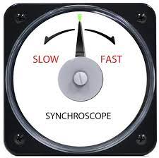
I remember decades ago as a turning a knob on the engineers panel of a 727-100 until two flashing light bulbs synchronized before toggling the bus tie switch. In the aircraft we support now (a newer tetradactyl), the generator control units and look for freq, current, voltage faults, and report to an electrical power control unit. Our airplanes do have a fairly detailed electrical synoptic display probably designed for the pilots, but it doesn't show us why when a GCU refuses to tie.

Typically the control unit issues cryptic codes and the parts cannon fires hoping to replace the faulty sensor, relay or generator in the hopes of making the message go away. It's not unusual for it to take several maintenance visits to resolve the issue. I can't help but to think there must be a better way.

My posts reflect my personal views and are not in any way endorsed or approved by any organization I'm professionally affiliated with.
 
Replies continue below

Recommended for you

In the stationary generator world we use protective relays for that. I’ve programmed an SEL 700G for a synchronizations check function (among many other things), and display the permissive states on the front panel for the operators. We’ve used that to troubleshoot multiple times.
Not sure that particular relay would be appropriate for your application, but it should be relatively easy in any intelligent electrical relay (famous last words, I know..)
 
Nope, most relays intended for power system use, be it 50 or 60Hz, don’t sample at anywhere near the frequency necessary to provide meaningful data about a 400Hz system.

I’ll see your silver lining and raise you two black clouds. - Protection Operations
 
Good point, I think it goes up to 75Hz (If I recall correctly from the manual)
 
For manual operation a synchroscope.
For automatic operation, a sync check relay.
There are advantages to a synchroscope and a sync check relay may be added to a synchroscope.
Three parameters must be within limits for successful paralleling.
Voltage, frequency and phase relationship.
Phase relationship is by far the most important.
A synchroscope has a single pointer capable of continuous rotation.
The RPM of the synchroscope is directly proportional to the difference in frequency of two sources.
Historically, best condition for closing the paralleling breaker is not equal frequency, but with the incoming set running at a slightly higher frequency. This allows the incoming set to pick up some load and avoid inadvertent reverse power trips.
When the sets are at equal frequency, the pointer will be stationery.
To synchronize, the speeds are adjusted until the pointer is rotating slowly clock-wise.
When the pointer is at 12 O-clock, the breaker is closed and the incoming set picks up some load.
A simple sync check relay will prevent serious mistakes, but will not be able to mimic the action of a skilled operator and a synchroscope.
For that you have to spend a lot more money for a more sophisticated synchronizing relay.

I have installed several residential standby generators, with Very Fast Transfer switches.
When the generator is running and the grid power returns, the very fast transfer switch has such close spacing between the normal contacts and the standby contacts that it is not safe to transfer unless the phase angles are equal.
The transfer switches have sync check relay that will not allow a transfer until the two sources of power are in phase.
The problem that sometimes arises is when the standby set is running at exactly the same frequency as the grid, but badly out of step.
It may take minutes for the phases to drift into close enough alignment for a safe transfer.
I have no idea as to what equipment that you have installed, but it may be possible that some failures to synchronize may be due to the sets running at exactly the same frequency but out of step.
Untitled_db0wqs.jpg


--------------------
Ohm's law
Not just a good idea;
It's the LAW!
 
For trouble shooting consider a dual trace oscilloscope.
Put a voltage signal from the same phase of each generator to a trace.
With the time base set so that one trace is stationary, the second trace will drift either to the right or to the left.
That will indicate fast or slow, not sure which.
When the traces are superimposed, the phases are in step for paralleling.
With the scope connected to the inputs of a sync check relay you will be able to check the operating points of the relay.

--------------------
Ohm's law
Not just a good idea;
It's the LAW!
 
Bill

Synchroscopes work in a very narrow band of frequency. Won't work at aircraft frequency of 400 Hz as also standard 50/60 Hz protection and measurement systems.

This is a safety issue. I don't think it's a good idea to trawl internet seeking to troubleshoot custom designed custom built electrical machines.


Muthu
 
Agreed, Muthu.
Thank you for your respectful comment.
I have edited my last post from scope to oscilloscope to remove ambiguity.
The oscilloscope will work at 400 Hz.
I understand that we can't suggest hacks for installation in aircraft.
I don't think that using an oscilloscope for troubleshooting on the ground will be an issue.
I think that it is safe to assume that there is aircraft specific synchronizing gear installed.
The principles of parallel operation are the same regardless of frequency.
Speed control must be about 8 times closer at 400 Hz.
How to trouble shoot problems with 400 Hz relays and equipment? One method is the oscilloscope.


--------------------
Ohm's law
Not just a good idea;
It's the LAW!
 
Or this:
Synchroscope_120V_400_Hz_Scale-_khsen9.png

And this:
Untitled_i3yh72.jpg

SYNCHRONISING CHECK
.
TECHNICAL SPECIFICATION
INPUT
Rated value Un 57.8<500V± 25%
Frequency 50 /60/400 Hz
Burden <4VA terminals marked GEN
<2VA terminals marked BUS
Overload 1.5x Un continuous
10x Un for 3 seconds
SETPOINT
Range Adjustable 10% to 30% of
nominal system voltage
(6-20 electrical degrees)
Repeatability Better than 0.5% of full span
Differential Fixed at 5%
Operating time Typically 500ms

--------------------
Ohm's law
Not just a good idea;
It's the LAW!
 
Here is a short discourse on voltage and frequency in regards to paralleling.

An overview on Paralleling:
Voltage;
What are the implications of unmatched voltages?
A typical generator supplies both real power and reactive power.
With two comparable machines in parallel, the respective voltage settings control the flow of reactive power, or reactive Amps.
Ideally, the machines should divide the reactive power in proportion to their KVA ratings.
Starting with the loads and reactive current balanced, what happens as the voltage set point of one machine is changed?
The higher voltage machine will supply a greater share of the reactive current.
As the voltage set point difference is increased, one machine will eventually be supplying all of the reactive current demanded by the load.
As the voltage set point difference is increased further, the reactive current will increase.
As the load demands have been satisfied, the excess reactive current will flow in the other generator.
Extreme voltage set point differences may lead to one or both generators becoming overheated and damaged.

Frequency:
For background I will review frequency (speed) control.
A signal proportional to the speed or frequency is fed to a proportional controller. (The P in PID controller.)
The controller is set to 3% proportional band with a 3% offset.
So at full load the generator will be running at 60 Hz (Or 50 Hz or 400 Hz).
At no load the generator will be running at 60 Hz+3% = 61.8Hz, 50 Hz or+3% = 51.5Hz, 400 Hz+3% = 412Hz.
Consider the grid as an infinite source. The addition of a relatively small generator will not change the grid frequency.
(Notes: for grid connections the droop is set to 5% instead of 3%. If our small set does have enough capacity to change the grid frequency, the grid swing set will cancel out the change so apart from switching effects, the grid will act as an infinite source.
How do we set the load that we want to place on our incoming set?
Adjust the set point of the P controller.
If the frequency is set to the grid frequency, the set will idle on-line but will not supply power to the grid.
If the frequency is set to the grid frequency plus 5% or 3% as the case may be, the set will deliver 100% of rated power.
So load control is affected by the frequency setting working with the droop setting of the controller.

Frequency and paralleling;
It is best if the incoming set picks up a little power when it comes online. This avoids reverse power trips that may occur if the instrumentation is off calibration a small amount.
For a first time, adjust the speed of the incoming set so that the synchroscope takes about 5 to 10 seconds to make a complete clockwise revolution.
Or, adjust the speed of the incoming set so that the oscilloscope traces take about 5 to 10 seconds to move one period.
Once you have the set in parallel, you can set the speed set point to pick up as much load as you want to when paralleling and use that setting prior to paralleling in future.
Take-aways:
1. Changing the frequency set point on an islanded set changes the speed and the frequency.
2. Changing the frequency set point on an grid tied set changes the amount of load picked up.
2. Changing the frequency set point on an paralleled with a similar set changes both the frequency and the amount of load picked up.

Phase angle: To come later.


--------------------
Ohm's law
Not just a good idea;
It's the LAW!
 
Status
Not open for further replies.

Part and Inventory Search

Sponsor