Continue to Site

Eng-Tips is the largest engineering community on the Internet

Intelligent Work Forums for Engineering Professionals

  • Congratulations KootK on being selected by the Eng-Tips community for having the most helpful posts in the forums last week. Way to Go!

Loose control on total width but tight control on edge quality

Status
Not open for further replies.

roller_delawer

Automotive
Jan 15, 2017
13
Hi all,

I have this rectangular part which I want to tightly control both edges profiles, but I want to give my supplier some freedome to produce longer or shorter parts (as long as the edge itself looks good).

It's almost like we want to create two different areas for each edge. One large area (green) and another small area (red). The profile condition will be good as long as the edge is within the red, and the red is within the green. Also, the red and green areas need to be alligned with x & y, as we can't accept a tapered condition.

To complicate the things a bit more, the locator that controls Y position is not centered, so the distance to one edge is different to the other. And none of us is sure how to make the GD&T for this particular case.
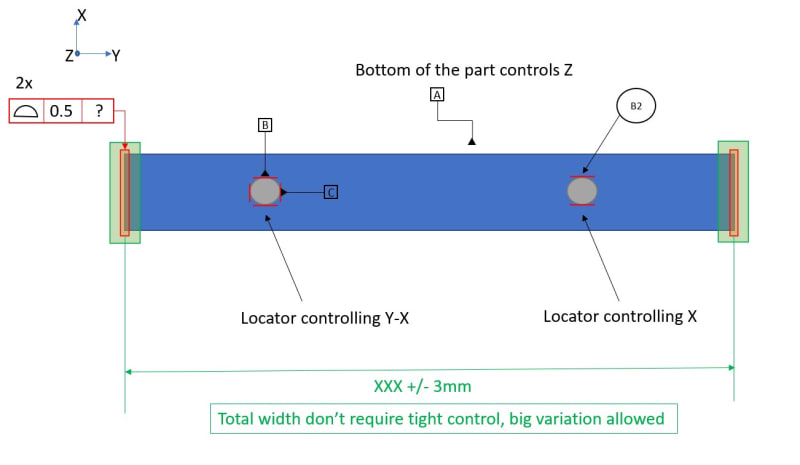

Tolerance_example_xjbqks.jpg


We're only sure of two things:

A) Profile of a surface to A|B|C. That will constraint the total width too, and will require to open the tolerance on the edge that is further from the locator. Not what we want.

B) Width dimension with large tolerance + Profile of a surface without datum reference. That will avoid the edge being wobly, but will open the door for a tapered condition.


Any help will be welcome!

Thanks
 
Replies continue below

Recommended for you

roller_delawer,

I do not agree with the way you show your datums. The first hole is your datum feature[ ]B, and it controls X and Y. The second hole is your datum feature[ ]C, and it controls rotation.

If you don't care about width, you apply a sloppy profile tolerance.

If want the edge to look cool, you apply controls to make it look cool. Straightness, Parallelism?

Read up on composite feature control frames (FCFs).

--
JHG
 
Hi Drawoh,

Thanks for your reply. That's the way we are usually asked to use the datums in my company. I agree it seems odd, but it does follow the general rule of constraining 3,2,1 dof.

Regarding the use of straightness or parallelism it's not possible unfortunately, as the edges are not really straight. I used a rectangle as an approximation, cause the part looks more or less rectangular in plain view. But in reality it's a quasi-flat part which edges follow a complex 3D curve, so the use of profile of a surface needs to be used.
 
It's almost like we want to create two different areas for each edge. One large area (green) and another small area (red). The profile condition will be good as long as the edge is within the red, and the red is within the green. Also, the red and green areas need to be alligned with x & y, as we can't accept a tapered condition.

Sounds to me like you're describing composite tolerance. Specify two separate composite profile tolerance zones for each edge, specified with SEP REQT the upper segment will control location of each edge separately in a larger, sloppier zone, lower segment will control form and orientation within a tighter zone - both wrt A|B|C. You could even specify a third segment without datum references to refine form if desired.

Regarding the use of straightness or parallelism it's not possible unfortunately, as the edges are not really straight. I used a rectangle as an approximation, cause the part looks more or less rectangular in plain view. But in reality it's a quasi-flat part which edges follow a complex 3D curve, so the use of profile of a surface needs to be used.

The part doesn't need to be rectangular, as long as the surface is flat. You say quasi-flat but as long as all points on the surface exist in the same plane, its flat in the direction we care about. You can apply parallelism instead of the second segment I mentioned above with composite profile. You can also apply flatness instead of the third segment I mentioned (datumless profile). You could probably even get away with just a directly toleranced +/- width between the edges and do away with profile altogether if you really wanted and use position to control location - but this would be center plane location (you probably care about the location of each edge not UAME) and assumes the edge is wide enough aka stable/reliable surface with enough opposed points. The previously noted profile might be the better choice in this regard.

That's the way we are usually asked to use the datums in my company. I agree it seems odd, but it does follow the general rule of constraining 3,2,1 dof.

Its more about the fact that you said the tertiary datum feature only constrains [x]. In reality it works together with your secondary datum feature to constrain [w] rotation around the z-axis. Theres more nuance to it even than that and I could write paragraphs about how this is technically overconstraint and what exactly constraint of [w] rotation in this manner actually is (and I have) but thats entirely too far in the weeds, this is the broad strokes and is good enough for most discussions.
 
chez311,
Could you clarify why in your proposed solution the SEP REQT would be needed in both upper segments?
 
pmarc,

You're right - thats not necessary, I have struck that line out. For some reason I was thinking it would constrain it as a pattern in location for the lower segments but of course the lower segments of a composite tolerance are SEP REQT by default. I confused myself, thanks for pointing that out.
 
Status
Not open for further replies.

Part and Inventory Search

Sponsor