Continue to Site

Eng-Tips is the largest engineering community on the Internet

Intelligent Work Forums for Engineering Professionals

  • Congratulations GregLocock on being selected by the Eng-Tips community for having the most helpful posts in the forums last week. Way to Go!

Lorry crashes into and demolishes pedestrian bridge.

Status
Not open for further replies.
I did some crude analysis of both the newspaper photo and yours. Yours is more obvious; when you draw in the perspective lines, the perspective line from the walkway goes under the gantry sign

TTFN (ta ta for now)
I can do absolutely anything. I'm an expert! faq731-376 forum1529
 
OK,

Some more digging (excuse the pun) finds a bit more evidence.

This pic is the best I've seen and given that the low loader is currently crushed under the weight of the bridge so probably 0.5m lower than it would have been and an eye witness report who heard a "loud bang", it looks like the digger arm hit the side of the bridge hard enough to hit it sideways off its support on the outside of the carriageway.

Now whether the bridge was as high as it should have been or the digger was over the maximum height is going to be the key question.

M20_bridge_3_ncmeaw.jpg


I think the timing of it, the fact it hit the lorry first and the now near universal application of anti-lock brakes saved us from a multi vehicle pile up. That and the bike rider who just managed to slide under the bridge as it collapsed.

Remember - More details = better answers
Also: If you get a response it's polite to respond to it.
 
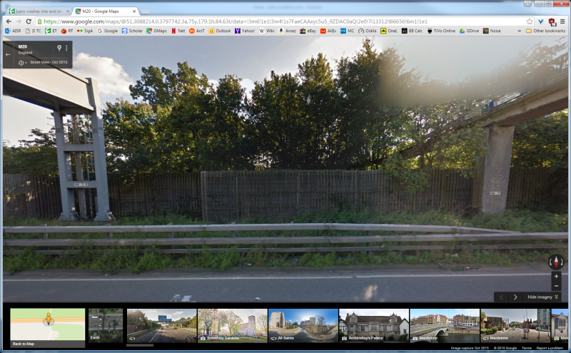
Here's the street view from Google Maps; I'd say the gantry is higher up than the walkway
Lorry_crash_ciaqfo.png


TTFN (ta ta for now)
I can do absolutely anything. I'm an expert! faq731-376 forum1529
 
The driver must have thought he was in the clear; he passed under at least 3 overpasses prior to the gantry sign and walkway

TTFN (ta ta for now)
I can do absolutely anything. I'm an expert! faq731-376 forum1529
 
JohnRBaker said:
I know that this is a bit off-topic, however, since we've been looking at a lot of pictures of excavators and other large yellow pieces of equipment, and I further suspect that many of us, when we were kids, may have had 'sand box' toys modeled after stuff like this. And so I thought it might be of interest to learn that there's a place outside of Las Vegas, NV where you can go and 'play' with the real thing:


I've been there, it's an absolute blast. Worth every penny.
 
IR stuff,

That's a good view, but exaggerates it a bit as the edge of the hard shoulder is the key bit as the bridge is definitely on a slope down. The modern bridges and gantries are apparently 5.5-5.7m, but the bridges only need to be 5.03 (16 ft 6") though whether that applied to the hard shoulder when they built the motorway is not clear.

either way its quite a bit less than the gantry.

Interestingly the HSE website quotes 5.1m (!) and the new super tall trailers are up to 4.9m. Definitely scary seeing those go under some of the bridges.

Remember - More details = better answers
Also: If you get a response it's polite to respond to it.
 
On a trip around Chicago and heading west on the Tri-state I came to stalled traffic. Decided to take my 4 x 4 Chevy Suborban down trough the median and up to the east bound lane. Luckily had the machine in 4 wheel drive and flooring accelerator pedal causing maximum RPM and with wife screaming, throwing mud all over creation I made it out. Could have been siting there a day and a heavy fine Next trip through that area I noted they decided against any such move and a median fence had been erected instead. Left at next exit and ate lunch there. Upon leaving restaurant, see the backup was not moving, so I took a parallel road home. One reason why now I use the old road instead of Interstate if no hurry and I have a more pleasant no traffic situation. At at age 88 I don't need any more such experiences or stalled traffic frustrations.
 
Looks if the truck had stayed in the rightmost lane, he might have cleared the walkway

TTFN (ta ta for now)
I can do absolutely anything. I'm an expert! faq731-376 forum1529
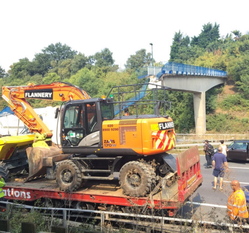
 
One thing that intrigued me was that the impact with the bridge did not displace the digger off the back of the flat bed.
B.E.

You are judged not by what you know, but by what you can do.
 
That digger is pretty heavy, at least 18600 kg. More importantly, the boom's design is such that the impact force is directed downwards, because of the curve in the boom. So, the force of the impact is actually magnified because, it's pushing downward on the truck, which won't give as much as it might have if the force were directed rearward against the digger. If you look at the curve of the main boom, it's as if it were designed specifically to redirect the impact force downward. More amazingly is the fact that the joint on the boom appears to be completely undamaged. Of course, this might have all been augmented by the lack of lateral resistance of the walkway. Kudos to Hitachi for building a supremely robust digger!

digger_tmnlz9.png


TTFN (ta ta for now)
I can do absolutely anything. I'm an expert! faq731-376 forum1529
 
Sorry for bumping an old thread but don't come here often and for some reason the title of this one got my attention.

Anyway, looking at the pictures of the pedestrian bridge, is it my imagination or does it not have much (any?) visible rebar where the break is?

Posting guidelines faq731-376 (probably not aimed specifically at you)
What is Engineering anyway: faq1088-1484
 
No its not your imagination. The design of this particular bridge is a bit odd and the section that feel off was basically a simply supported beam resting on two supports. The far side of the bridge is a much more solid cantilever....

Remember - More details = better answers
Also: If you get a response it's polite to respond to it.
 
Two separate pre-cast sections lifted into place, held there by gravity and the grace of God. And maybe a little engineering judgement that didn't foresee forty-odd tonnes hitting it at 56mph...
 
Apparently the lorry hitting it was crawling along the hard shoulder so 5.6 mph would be closer. ... Does seem remarkable that it was essentially gravity holding it all together for the last 25 yeasts.

Remember - More details = better answers
Also: If you get a response it's polite to respond to it.
 
Not too odd. "Cantilever" style bridge construction with a "suspended span". Fairly efficient, and very constructable.

Although I'm most used to seeing it for large steel trusses over waterways -- lower collision risk there!

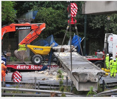
lifting_large.jpg
 
Got it, it was the location of one of the 'simple supports' that was throwing me off.

Posting guidelines faq731-376 (probably not aimed specifically at you)
What is Engineering anyway: faq1088-1484
 
Missed that, thanks LittleInch.
 
Lomarandill,

To me, though I'm far from an expert, the odd thing is that there is one long cantilever over about half the span / motorway, then this beam between the end of the cantilever and what is basically a pin support. If you look back at the google streetview images I posted on 30/8 at 0843, you can fairly clearly see the beam section ends. The first half cantilever stood the test and was suspended over the motorway until it was demolished a few day later.

The design is also strange as the bridge deck is clearly on a slope down from one side to another but also narrows down as it gets to the far side.

I think someone went a bit too far trying to save on concrete and the height of stairs on the far side. This is a pedestrian bridge which then has a circular walkway on the side it was hit.

If anyone had actually been on it when it was hit it's fairly clear they would have died. how no one else was seriously injured is a minor miracle which might not happen next time.

Remember - More details = better answers
Also: If you get a response it's polite to respond to it.
 
LittleInch said:
there is one long cantilever over about half the span / motorway, then this beam between the end of the cantilever and what is basically a pin support

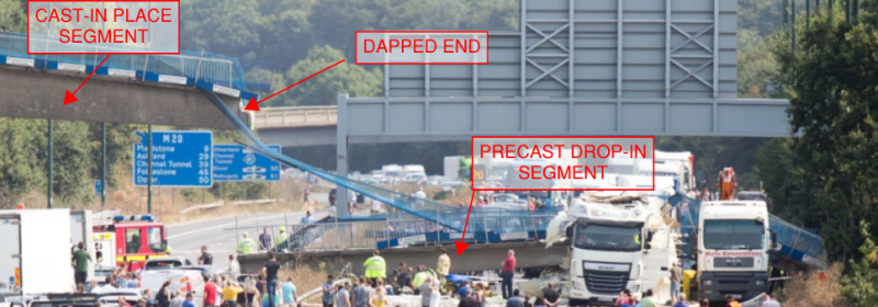
LittleInch, what you describe is pretty much the framing, using what appears to be cast-in-place section with dapped end (on the left), then the a precast drop-in (maybe should be retitled 'drop-down' :-0), with the far right end of the precast supported in a simple seat over the pier, as per below tagged photo:

Capture_zpbdij.png


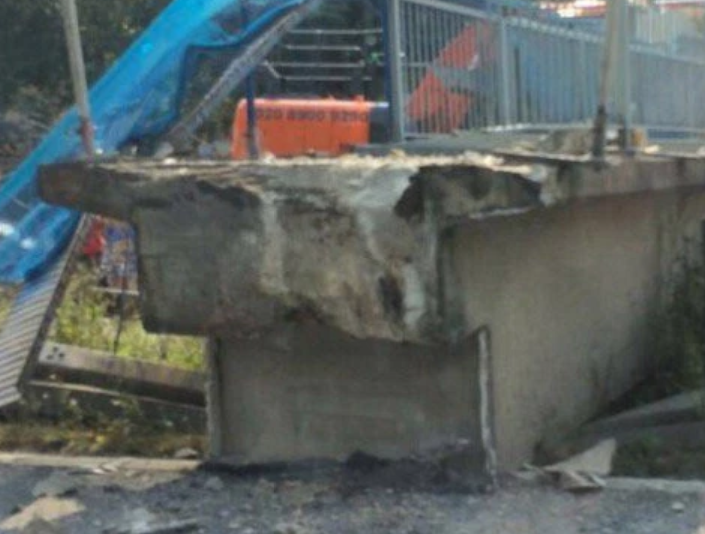
The dapped end of the precast segment, in detail:

Capture1_npyabg.png


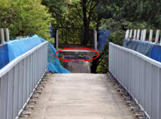
The far right support end over the pier:
Capture2_u5jmkx.png


This is somewhat common framing, using precast segments, and cast-in place too. Evidently, the lateral capacity of the simple seats is questionable.
 
Status
Not open for further replies.

Part and Inventory Search

Sponsor