Eng-Tips is the largest engineering community on the Internet

Intelligent Work Forums for Engineering Professionals

  • Congratulations waross on being selected by the Tek-Tips community for having the most helpful posts in the forums last week. Way to Go!

Lotus 907 Bearing Panel Stiffening

Status
Not open for further replies.

dakota123

Mechanical
Jun 11, 2012
4
0
0
US
Hi there,

I'm planning a high-performance rebuild of a Lotus 907 engine, which is an all-aluminum (except for cylinder liners) 2.0L (stock) 4-cylinder, DOHC, 16-valve, dating to the early '70's. It was used in the Jensen Healey originally; once the remaining development issues were ironed out this engine was used in the Lotus Esprit, Elite, and Eclat. Later, due to the issue I'm trying to resolve, the bottom end was redesigned and the engine was designated the 912.

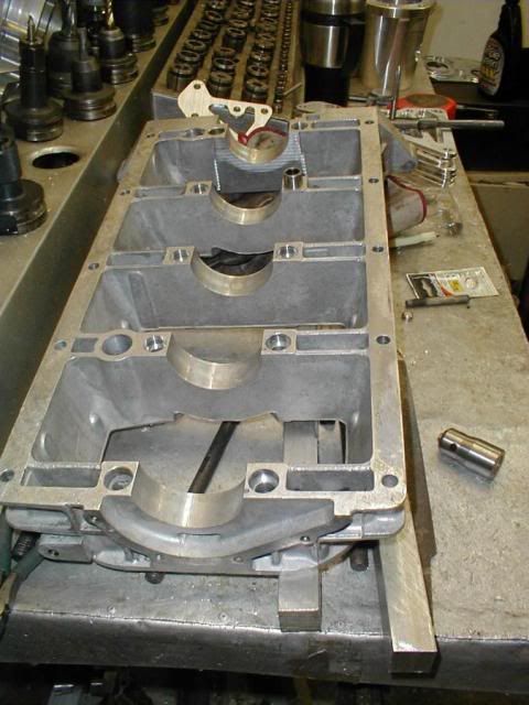
The block is made up of three pieces, the block-proper, a lower panel that incorporates the main bearing caps, and the sump (which itself has structural significance).

The 907 is very oversquare and consequently has a high rpm torque peak, which makes daily driving, especially in traffic, a bit challenging. One way to deal with this is to increase stroke by fitting a crank from a 2.2L (with associated piston change). This is a drop-in, except that by all accounts the bottom end is not rigid enough to support extended enthusiastic driving (say, track day) for any length of time. Bearing failure is the typical result. (This is why Lotus eventually redesigned the bottom end.)

Experienced 907 builders typically recommend that the way to make the 907 live with a 2.2L crank is to add locating dowels between the block and the bearing panel. From the factory, only two dowels are fitted, one each at the No. 1 and No. 5 bearings. Builders recommend that eight more be added, so that each main bearing has two dowels locating the bearing panel to the block. (The dowels are hollow, 15mm I believe, and fit around each main bearing stud.)

What I'm wondering is if maybe there is a better/more modern way to attack this problem, with adhesive. In other words, use adhesive on the bearing cradle-to-block join rather than additional dowels. (Anaerobic sealer is already used at the outer flange for oil-tighness, but not typically along the bearing lines.)

The reason I'm thinking along these lines is that what was originally spec'd to be a cork-gasketed join between the sump and bearing panel is now advised to be essentially metal-metal, sealed just with Hylomar. (In fact, some builders advise that the added rigidity gained by eliminating the sump gasket is enough to solve the flexibility issue, although I would like added piece of mind...) Also, this engine is pretty buzzy at high RPMs, and intuitively adhesive would make the structure more "of one piece".

If this doesn't seem like a completely FUBAR idea, can someone recommend a suitable adhesive? (I haven't been able to determine what type of aluminum is is...)

Thanks for any advice, encouraging or discouraging the idea...
 
Replies continue below

Recommended for you

IF I thought adhesive was a better solution than multiple dowels (I don't), I'd probably use a thin red Loctite, with appropriate cleaner.

There is, however, an associated problem. If the Loctite bonds well enough to stiffen the assembly, you'd better hope you never have to change or inspect the bearings, because you'll have to heat the assembly to a little over 400F to weaken the bond. I think that will change the temper of the aluminum and possibly distort it, too. So the engine becomes a throwaway, probably not an outcome you want.


Mike Halloran
Pembroke Pines, FL, USA
 
Add to this the possibility that some of that Loctite, if it comes in contact with any oil, will come loose and clog the oil filter. I read about this happening-- an engine builder supposedly used red Loctite (!) on the connecting rod bolts. When the engine seized, the filter was found to be plugged full of red gunk. Don't know if it's true, but it was documented in an engine book I read (possibly 1001 High Performance Tips by Wayne Scraba, but I can't recall for sure).

I've seen small block Chevrolets add 4-bolt main caps with splayed (angled) outer bolts. Milodon makes the caps, IIRC. In Chevy blocks, ths ties the main caps into the main bearing webs, and the bolt angle keeps the caps from walking. Any chance a similar approach can be made to work with your engine?
 
Thanks so far to respondants...

Throwing the block away wouldn't be horrible (except maybe to the purists who would bemoan one less block out there) -- they can be had for $150 or so, and the liners, crank, accessories transferred over.

I admit the engineer in me is reluctant to make something, anything, a throwaway, but I am still intrigued by the possibility of "fixing" this throwback to a different era using modern methods. Intuitively it seems to me that using the proper adhesive (and getting that product to adhere) would be more effective than the dowels -- I don't think the dowels are really all that effective at limiting flex, only that they get the system "over the hump" as it were, and make rigidity acceptable but not a mm more.

There isn't enough room to add splayed bolts, unfortunately...

Anyway, thanks again. Not sure which way I'll go at this point.
 
I would not entertain using an adhesive on a main bearing cap parting line as it can alter bearing crush.

Tube dowels are what Carrillo use on the parting line of their rods and they seem like a good example to copy. Some other top end rod manufacturers use smaller solid dowels near the bolt holes, but they all use dowels and none use adhesive. There are good reasons for that I believe, some of which are listed above.

Bigger bolts, more bolts might be applicable, but that depends on existing bolt size and web design. Will higher clamping force offset metal removed from the web?

Out of interest, on a 400CI small block Chevy, The factory 2 bolt block is the preferred high performance starting point as it leaves more metal in the weakest part of the web. The two bolt blocks are then converted to splay bolt 4 bolters as the splay bolts thread into a stronger better supported part of the web just by the sump gasket rail and the outside wall of the block.

A steel girdle in place of the aluminium one would substantially reinforce the main cap system, but creates it;s own issues with increased weight, but more importantly with differential rates of thermal expansion and the consequential impact on dimensional stability.

Once again, very high performance SBCs tend to use steel caps on both aluminium and iron blocks, although that is more for crack resistance than rigidity.

Regards
Pat
See FAQ731-376 for tips on use of eng-tips by professional engineers &
for site rules
 
I haven't seen your lower end. From your description, it appears to me that an enhanced "lower panel" milled from a billet of very strong wrought aluminum alloy (7075, etc.), along with the pair of hollow dowels at each main would be the answer. Hopefully, you could enlarge dimensions wherever possible, to even further enhance rigidity. [I've had good results with billet aluminum main caps dowel-located on the cast aluminum block of my 900 HP blown-alky engine]
 
Here's a picture of the bearing panel; you can see one of the dowels installed. (Not my engine.)

MBC_Dowel_Holes_Completed2.jpg


The dowel holes surround each bearing stud. For severe duty (i.e. a season of 7-8,000 rpm running), some builders will fab a steel stiffener panel, adding it between the bearing panel and the sump. (The bearing panel and block are a matched set) between the bearing panel and sump. This engine mounts typically are then attached to this new piece, relieving the block from that duty and of course stiffening the entire assembly.

This raises the height of the engine by 0.5" or so, which introduces a host of other issues. All solveable, but more effor than I'm willing to endure. And, I'm not going to campaign the car, just take it to the occasional track day.

Think I'm just going with the tried-and-true dowels...

Thanks again.
 
There is not much "footprint" between the block and that bearing panel.

inline 4 cylinders are "buzzy" due to secondary unbalance.
The twice-per-revolution forces are pretty much all upward along the cylnder centerline.
So although the crank is getting tugged vertically in the block 2X the main bearing caps don't see much of it.

Pairs of high revving counter rotating "balance" shafts with the correct amounts of unbalance built in can reduce the secondary vibration transmited to the vehicle to a remarkable degree. The forces on the crank are not reduced by the use of "balance" shafts

I wonder if the preceived buzziness of the stroker engine is the result of using the under-weighted OEM balance shafts.
 
FYI the Porsche 944 engines use a similar girdle (panel) and the girdle is spec'd to be sealed to the block with LocTite 574. In that case it isn't specifically for any structural benefit, rather because the oil pump inlet passages are in the girdle and must be sealed. But it couldn't hurt... Interestingly, the girdle uses only two dowels, one front/one rear, on engines that were producing 230 HP from the factory, and are routinely tweaked to 300+ (turbos). Makes me suspect there is more at play here on the Lotus engine...

MainBearinggirdle.jpg
 
The Lotus appears to be effectively a "2 bolt" main bearing design.
The Porsche loks like a "3 bolt" at least on the intermediate main bearings. Are the oil passages in the section to the right, with 3 bolts?
 
Tmoose, yes, that is the purpose of the "extra" bolts, the channel for oil pickup runs right under the ribs. You can see it to the right in this pic (ignore the red circle)

MainBearinggirdle-2.jpg
 
I would not dowel the bottom end. I am building a 907/912hc hybrid, and had thoughts of this too (since jhps seems to recommend this). Problems are created by doing this. First, after doweling, most of the time the main bearing surfaces will have to be line bored. If you are really lucky, maybe a light hone, but it normally does not turn out that way. Once you linebore the mains, you have to source larger od bearing shells, and not many, if any of those seem to exist anymore. So with more work, you end up using chrysler 318 mains. For true racing apps, that is what most do. Pretty expensive to do - some say around a grand.

I spoke at length with Jeff at Jae, Richard at West Coast Cylinder Heads, and Garry Kemp in England (probably the foremost builder of lotus engines in the world). All recommended against going the dowel route, mainly from the above problems. If I were to add dowels, it would probably just be on the #3 main.

According to Garry, he has built JH blocks to 215-220hp without doweling, with no problems. The root of most of the bearing problems are due to oiling problems, not flex. The biggest fix to start with is using an oil restrictor in the block to limit the overall flow to the head. Stock, that is about a quarter inch hole. I am using a stainless 5/16 set screw with a .100" hole in it, tapped the block, and screwed it in. That keeps from over oiling the top end, and ending up with a quart or more oil retained in the cam covers. If it is going to be a real high rpm build, I have been recommended to consider going as small as .060" on the hole.

That restrictor also helps to not have oil pressure drop to 5 pounds or less when the engine is hot. By restricting the oil to the head, the bearings end up with more pressure and better oil flow.

Other things that can help on the left hand oil pressure drop on these motors is better baffles in the oil pan, but with the restrictor, I don't know that will totally be necessary, unless a total out and out race motor.

I too will not be using the pan gasket, but most likely will use the same loctite as used under the cam carriers (517?).

Another thought on track days would be to throw maybe an extra half quart or so over full of oil in the engine.

Other thoughs on these engines -

Porting can help a bunch on the head. Best starting point is doing a good bowel port job, and consider working the runners some. I brought in a 912hc head used from England as a starting point - larger ports, no air injector holes, and supposed to have better water paths in the head. I spent a month doing the porting myself, using sanding drums. (hour or two at a time) I also ported, and port matched the 912hc intake manifold. Will be running spec 10 lotus dellorto tri jet carbs from the same 912hc motor (dhla 45d's). My 2.2 crank is also a used cross drilled 912hc crank. Richard was impressed with my porting (for a first timer!) - he currently is doing the valve job, new bronze guides with seals, new stainless valves, and going to skim the head, and shim the cams. Should be done late this week.

I am sticking with stock sized valves, and using a L14 kent intake cam (very close to 104 specs), and a lotus 107 exhaust cam. Thought here was to make something that will rev, but not destroy lower end torque, and still maybe even get great fuel economy.

HTD round tooth pulleys (104 mop), going to 97mm overbore forged pistons (either je or cp) at 10.5 or 11 to 1. That is almost .070" over the stock cylinder bore, and what Garry recommended as max without creating new problems. That will bring the displacement up to 2290cc's (about 140 cubic inches) from the original 1976cc's. Lightweight chrome moly h beam rods, lightweight chrome moly cam followers with the extended height, stock 912hc springs. 1984 turbo esprit steel flywheel (12.2 pounds verses the stock 19.4 pound cast iron stock flywheel). All those changes will net close to 10 pounds out of the engine/flywheel, and that is all stuff that either goes round, or up and down.

4-2-1 headers, to again help the bottom end. I hope to build around 225hp peak at say 6500-6800rpm, but still pull to 7500. And looking for around 28mpg. This is going in a '77 lotus esprit s1 - matching numbers block. (< 2200 pounds)

I started the rebuild from the air cleaner in. When the head returns back from Richard, everything is done on the top end, and time to start building the bottom end.


Here is how it is looking so far -

porting.jpg

carbs.jpg

topend_001.jpg


Brian
 
Thanks for including the pics -- beautiful work.

My thinking mirrors yours right on down the line. I have a "Skip Brown" clone (needs guides installed but otherwise is in perfect shape), 10.5:1 pistons, 104/107 with HTD "green dot" and Del 45s (with Spec 10 parts ready to go in). I conversed with Gary via e-mail a time or two, and (via e-mail, anyway) he didn't sound quite as definite re: dowels not being a necessity below ~220 HP so I'm glad to hear you say that. He did say that "six-doweling" (both sides rather than one at the 1 and 5 bearings, and both sides of the No. 3) rather than 10 would be more than adequate. So I guess that's consistent.

I could never get Richard to return my calls; figured he wasn't interested in 907s anymore. Oh well.

Even when hot my existing engine with 102,000 miles on it still has 25 psi at idle and 50+ off idle. I've heard others say low oil pressure is a problem, but I haven't seen it.

Now, if I can finish up by other project soon (Audi 2.7T Frankenturbos instead of the K03s) then I can get back to the 907.


Thanks for chiming in. Much appreciated.
 
Best time to catch Richard is around 8am pacific time when they open (suggested by them). If you email, he will generally get back to you in a few days. Most of their work now is doing cnc 5 axis porting on chev LS7 heads. They still do the lotus heads by hand. Once you get him on the phone, he is quite knowledgeable, friendly, and with me has spent more time on the phone than I deserve considering my job is just assembly work, not a very big dollar job. He seems to love to talk about lotus stuff, even though they are not as involved as they were years ago.

Yep, asked Garry on the dowels, and I suggested just doing #3 if any at all, and he was in agreement. My original in the day esprit s1 would drop under 5 psi at idle. Maybe your motor has already had the restrictor installed. I recommend 500% on doing that if nothing else to your motor when it is down.

My motor had 80k miles on it, sounded fine, did not hear piston slap or anything, decent oil pressure, but decided to pull the head and take a look. #4 had way too much slop, so I suspected skirt damage. I also noticed the carbon stripe was wider on #3 top of cylinder than the others, so I expected the upper compression ring was broke. I have a buddy who is a master mazda mechanic look at it, and he thought I was all wet about the slop in #4, and the carbon width of #3, and to just put it back together. After full tear down, found #4 was burned badly on the skirts (and was starting to lock crooked in the cylinder - it was ready to totally gernade), cylinder now out of spec for that hole, and sure enough when I removed #3 out of the block, the top ring was in two pieces.

Does indeed sound like we are into very similar builds. Good luck with your build, and sounds like you will have a beaste audi on your hands!

Regards,

Brian in Parkersburg, WV
 
Status
Not open for further replies.
Back
Top