Continue to Site

Eng-Tips is the largest engineering community on the Internet

Intelligent Work Forums for Engineering Professionals

  • Congratulations KootK on being selected by the Eng-Tips community for having the most helpful posts in the forums last week. Way to Go!

Low Voltage THD But High Current THD 6

Status
Not open for further replies.

edison123

Electrical
Oct 23, 2002
4,426
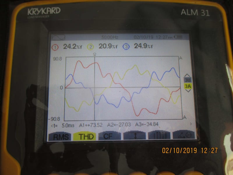
In our facility, we have a few 3-phase, 5 & 10 KVA and a few 1-phase, 3 & 5 KVA battery based UPS, many LED lights along with lathes, drilling machines, boring machines, milling machines electric cranes etc., which all have 3-phase motors. I did a voltage and current waveform check today as below.

Voltage THD - Less than 3%
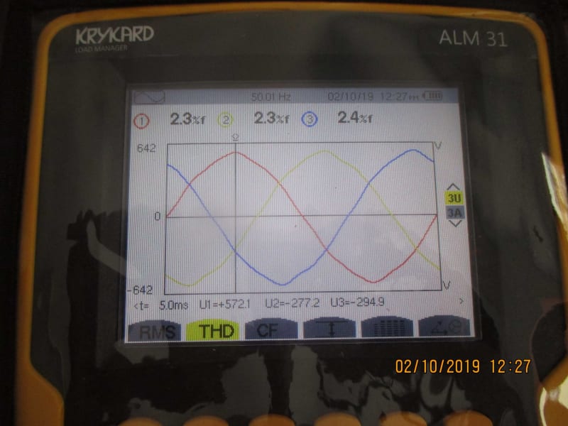
Volts_x8gxtr.jpg


Current THD - Over 20%

Amps_vcc53i.jpg


I found switching off the UPS one by one helped reduce the current THD to less than 5% thus confirming they are the culprits.

1. Is this high current THD normal when the voltage THD is so low?
2. Is such high current THD detrimental to my facility?
3. Do I need any passive or active filters or chokes at the supply side (front end) of UPS for harmonics mitigation?
4. If yes, should they be individual filters/chokes for each UPS or one big filter/choke at the incomer mains?

Thanks for your suggestions.

Muthu
 
Replies continue below

Recommended for you

The UPS will cause the current distortion. The voltage distortion is created by the voltage drop when the current harmonics flow. So, yes what you see is possible if the system impedance is low enough.

If you do want to add passive filters, they would go at each device.

You're likely OK if you're not having issues with equipment acting up or failing in your facility.

 
Thanks Lionel. As of now, we do not have any equipments or machines failure but a bit worried about future failures due to current harmonics.

No need of active filters? Only passive filter for each UPS will do?

Muthu
 
You could install an active filter at your MCC, but I doubt you'll find it's very cost effective for 75A or less of load. I'm doubting you could find a right sized filter so it'd have to be oversized.
 
Could be wrong...but I would think if V-THD was above 5%, then I'd start to think about filtering. I've seen I-THD above 30% with no ill effect.

Mike
 
Thanks, Lionel. Oversized filters will have its own issues, right?

Thanks, Mike. Do the utilities have any rules about permissible V-THD and I-THD? IEEE 519 says 5% V-THD limit with the largest single harmonic being no more than 3% of the fundamental voltage. Is there any standard that sets I-THD limit?

Muthu
 
I see the IEEE 519 current THD limits as an attempt to control the voltage distortion under various source impedances (system configurations). It's the resulting voltage distortion that creates problems.
 
Harmonic current causes higher losses in transformers.
 
I-THD is what causes V-THD. I-THD is caused by the way non-linear loads draw current, but is only your problem in your facility and is affected by the size of the service, in that what makes the most difference is the ratio of load current to available current. In other words if your load current is only a small portion of the available current (aka Fault Current) in a system, a high I-THD may have negligible effects on the V-THD, and vice versa.

V-THD travels to your neighbors via the common connection with the utility service. So IEEE519 was established to limit the V-THD at the PCC (Point of Common Coupling) and applies to you, the user CREATING V-THD with your I-THD, as well as the utility maintaining circuit impedance in order to not cause additional I-THD.

Bottom line, if you are showing only 3% V-THD at your PCC, it makes no difference what you see in terms of I-THD of an individual load. You are in compliance.


" We are all here on earth to help others; what on earth the others are here for I don't know." -- W. H. Auden
 
Thank you very much, Jeff, for the clear explanation.

The THD's were measured at my transformer secondary (wye). Will they show the same values at the transformer primary (delta), which is the PCC? i.e. Will the trafo impedance attenuate the harmonics at the primary?

Muthu
 
Muthu,
Currents no (except for trapping of triplens in a delta), but voltages yes (voltage divider between the transformer impedance and the system impedance).
 
edison123 said:
Any reason why current harmonics won't be mitigated by the transformer?
As with any current, the primary winding harmonic current is directly proportional to the secondary winding current. Triplens are trapped in a delta-wye transformer because the primary line currents are vector differences of adjacent winding currents. Triplens are zero-sequence and are identical in all three windings, so the vector difference is zero.
 
The nonlinear load acts (to good approximation) as a harmonic current source. Those harmonic currents flow all the way back to the system generator neutral point(s) (except for the triplens which may stop at a star-delta neutral). The harmonic voltages are a result of the volt drop from these currents flowing through the system impedances - hence if you have your transformer impedance in series with the rest of the upstream system impedance, the voltage at the connection point is the voltage divider ratio of the impedances.
 
One minor point, which is alluded to by aussiejohn…

Triplen harmonics are only trapped in the delta if you have a balanced system.

Mike
 
mparenteau said:
Triplen harmonics are only trapped in the delta if you have a balanced system.
That's a good point and seldom made. I once made harmonic current measurements on the source side of a delta-delta transformer serving an arc furnace. There was a high third harmonic component (average 13%) which was not trapped by the delta winding. Arc furnace currents are not balanced.
 
Status
Not open for further replies.

Part and Inventory Search

Sponsor