Continue to Site

Eng-Tips is the largest engineering community on the Internet

Intelligent Work Forums for Engineering Professionals

  • Congratulations KootK on being selected by the Eng-Tips community for having the most helpful posts in the forums last week. Way to Go!

Lower tailwater elevation causing higher water surface stages?

Status
Not open for further replies.

needcoffee

Civil/Environmental
May 27, 2011
4
I have modeled an existing stormsewer system using ICPR (version 3.10) for a neighborhood (existing stormsewer is undersized). I am analyzing 3 different tailwater elevations for the same storm event (10 year elevation from FEMA FIS Study, crown of outfall pipe, and invert of outfall pipe - FIS is the highest). For those unfamiliar with ICPR, you can create different boundary stage conditions and run them in separate routing files. This enables me to have 1 file that contains the exact same input for my stormsewer, node stage-storage, etc, but route the system for different tailwater conditions.

The output for my water surface stage elevations at each inlet seem to be valid for both the FIS tailwater and crown tailwater, but a couple of the systems are showing higher stages using the invert TW condition, than that of the crown TW condition. I am unsure why the lower TW would create higher stage elevations in some nodes (when compared to the crown TW and same node). The model has multiple outfall locations and there is a lot of roadway overtopping from one node to another and some basin transfer from one outfall system to another.

Could a flow regime difference be the cause? Mass balance report looks good and nothing is jumping out to me on the flow v time and stage v time graphs. I've included a table showing output elevations. The table includes the delta between the max stage and 1" over the roadway crown (design criteria). Anything red is bad as we are exceeding allowable ponding. You can see that some of the positive deltas for the Invert TW are larger than than that for the Crown TW.

Thoughts?
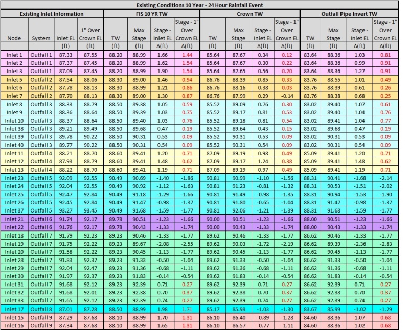
Stage_Table_mumocl.jpg
 
Replies continue below

Recommended for you

This is a fascinating problem.

Before jumping down the flow regime rabbit hole, I would take a closer look at this:

The model has multiple outfall locations and there is a lot of roadway overtopping from one node to another and some basin transfer from one outfall system to another.

Particularly since ICPR is typically a flat-system software and flat systems are typically all subcritical regime anyway.

Are all your outfall locations on the same TW?

Something clearly screwy is going on, and I wouldn't trust the model without a little more investigation. My ICPR experience is limited. Would it be easy to input, say, ten different TW conditions and run them all, compose them, and make a note of what TWs start the funny hysteresis you've identified? That might give you some insight into what's been modeled strangely. I suspect it has something to do with the basin transfer elements i the model, but I wouldn't put money on it.


Hydrology, Drainage Analysis, Flood Studies, and Complex Stormwater Litigation for Atlanta and the South East -
 
beej67,

This has really stumped everyone in my office and at the other, prime consultant. Ultimately, we have decided to not include the invert TW condition as the receiving body would never allow those circumstances, we originally modeled it to see how the stormsewer would perform under ideal conditions (or what we thought would be ideal...). I'm still determined to figure out what is going on though.

To answer your questions:

--Are all your outfall locations on the same TW?--
All the outfall locations ultimately end up in the same receiving body of water, but due to their location, have different values. Each independent outfall was given its elevation in a boundary condition. For instance, a boundary condition for Crown TW was created and within this condition, Outfall 1 has a value, Outfall 2 has value, etc. I then created 3 routing files, and in each one, they command the outfalls to use the boundary condition I created (e.g. Crown TW). I hope this was the answer you were seeking.

--Would it be easy to input, say, ten different TW conditions and run them all, compose them, and make a note of what TWs start the funny hysteresis you've identified?--
I've ran the model with TW conditions that are 0.3, 0.5, 1.0, and 1.5 feet above the Invert TW elevations at each outfall. No change in stages occurred for the 0.3 and 0.5 feet increase. At 1.0 feet and then 1.5, the max stages differences (between Invert TW and Crown TW) started to close the gap, but were still higher than the crown elevation. The closer I got to the Crown TW, the closer the max stages got.

--I suspect it has something to do with the basin transfer elements i the model, but I wouldn't put money on it.--
I also ran our existing model with every overtopping weir turned off to see if basin transfer, or just the amount of weirs in general, were affecting the model. Results still showed the Invert TW condition having higher max stages than that of the Crown TW.

Also, to note, for my pipe entrance/exit loss coefficients, I am using 0.5 for the entrance loss, and 0 for the exit loss (except at the outfall pipes, exit loss set to 1). I had wondered if because the low Invert TW creating an inlet controlled condition, maybe my 0.5 entrance loss was created the issue (vs the exit loss of 0 and outlet control conditions with the Crown TW). I re-ran the model using 0.5 for both my entrance and exit losses (kept 1 for outfall pipe exit loss). Results still showed Invert TW condition having higher max stages than that of the Crown TW. Re-ran with 0 for both entrance and exit loss and same situation.

Not sure what else to try...open to suggestions!
 
Have you e-mail Pete at ICPR? If you have an active service agreement he's generally able to explain the problems with your model pretty quickly. Better hurry though because support for version 3 ends on July 1.
 
I'm unclear what "invert tailwater" even means in pipe discharges, honestly. Is ICPR doing gradually varied flow calculations through the pipes? Standard step method? Direct Step?

Walking through the math conceptually.. ..to compute a subcritical flow profile you need a starting elevation at the downstream junction, which may or may not be your tailwater elevation. Your options really for that are:

* Normal depth, which would approximate tying to a flume or pipe system similar to the one you're modeling, (aka "the pipe keeps going")
* Crown, which would approximate tying to a system at capacity,
* Critical depth, which would indicate your pipe is hanging in space and the water is falling out, passing through the Yc value as it transitions from subcritical to supercritical flow,
* Some known tailwater value.

Then in a subcritical profile, you calculate backwards from that number. (in supercritical flow you calculate forwards from a number until you hit a jump or slope transition)

So when you input the invert value, are you inputting that value by hand, or just picking "invert" as a canned option in ICPR? If it's trying to use the actual invert as an actual starting elevation for a GVF profile, it'll blow up because a tailwater at the invert would mean zero depth of flow, which means infinite velocity by continuity. I'm unclear how ICPR handles that.

There might be some detail buried in the ICPR documentation that says "don't enter tailwater values lower than Yc."

Hydrology, Drainage Analysis, Flood Studies, and Complex Stormwater Litigation for Atlanta and the South East -
 
..all that said, I thought ICPR was mostly for reservoir routing, not for GVF flow profile calculations.

Hydrology, Drainage Analysis, Flood Studies, and Complex Stormwater Litigation for Atlanta and the South East -
 
beej67,

You sparked some ideas. The way my tailwater is modeled is through a time - stage node that the outfall pipe link is connected too. I have these set up for 0 hours xx.xx elevation and 24 hours xx.xx to set a constant tailwater. For the invert TW, I'm using the invert elevation at time 0 and 24. Within the Link, you can select the outlet control specification, which is set at "TW or dc" for my pipes except at the outfall pipe it is set to "TW or dn" which is recommended by ICPR. This selects the higher of the TW or normal/critical depth.

I just tried changing the "TW or dn" for my outfall pipes to "TW or dc" and now my numbers are acting normal, with either the Invert TW max stages at or below the Crown TW max stages. I'm guessing because the system is surcharged so much, using the normal depth at the outfall pipe is jumping up my HGL?

P.E. & Esq. = Lawgineer
 
This is not my area but I have done some basic storm water design using established flow equation but not ICPR. I am inclined to believe that some segments of storm water piping have deficient gradients. Does the mass balance include the mass of storm water held back when ponding occurs?
 
beej67,

You sparked some ideas. The way my tailwater is modeled is through a time - stage node that the outfall pipe link is connected too. I have these set up for 0 hours xx.xx elevation and 24 hours xx.xx to set a constant tailwater. For the invert TW, I'm using the invert elevation at time 0 and 24. Within the Link, you can select the outlet control specification, which is set at "TW or dc" for my pipes except at the outfall pipe it is set to "TW or dn" which is recommended by ICPR. This selects the higher of the TW or normal/critical depth.

I just tried changing the "TW or dn" for my outfall pipes to "TW or dc" and now my numbers are acting normal, with either the Invert TW max stages at or below the Crown TW max stages. I'm guessing because the system is surcharged so much, using the normal depth at the outfall pipe is jumping up my HGL?

Your problem continues to fascinate me.

I'm not sure why ICPR would do that.

Is ICPR actually doing a GVF calculation through the pipes, and if so, can you post a screenshot of the two profiles for comparison? Do you happen to know whether the flow in the last stick of pipe is subcritical or supercritical?

Do you know much about gradually varied flow profiles? Are the profiles M1, M2, M3, S1, S2, S3, etc? Which is higher in the pipe, the NDL or CDL?


Hydrology, Drainage Analysis, Flood Studies, and Complex Stormwater Litigation for Atlanta and the South East -
 
Status
Not open for further replies.

Part and Inventory Search

Sponsor