Continue to Site

Eng-Tips is the largest engineering community on the Internet

Intelligent Work Forums for Engineering Professionals

  • Congratulations MintJulep on being selected by the Eng-Tips community for having the most helpful posts in the forums last week. Way to Go!

LTB for Unitized Assembly (includes schematic)

r.borghino

Structural
Nov 25, 2024
10
Hello!
Context: We have a question regarding assumptions for a unitized curtain wall, where the main structural component is a male/female aluminum beam assembly. Typical spans anywhere from 10ft to 15ft.
-The usual assumption by contractors (which we think is incorrect) is to assume that each half-profile is fully braced and Lb=0, or that Lb=distance to nearest snap joint clip (Lb=roughly 2ft). Or Lb=L/3. Assuming the "brace" is infinitely stiff.
-If I check by ADM 2020, evaluating each "half-profile" independently, the allowable moment for LTB decreases drastically, which I also think is not a reasonable evaluation. (having witnessed a few wind load tests already for these types of profiles - LTB is only an issue for only the most slender of shapes where they are already well outside the allowable deflections anyway)

The Problem: Some options, some better than others.
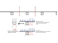
1.- We were suggested to calculating the LTB moment using the slenderness formula for "Closed Shape" (F.4.2.3), but plugging in the J, Ix and Iy of the male and female halves added together. Lb= real distance to nearest transverse profile.
2.- under certain loading conditions (positive wind pressure) the compression flange is arguably actually continuously braced against LTB by the structural adhesive bonding with the glass and LTB becomes a non-issue. Therefore, LTB is a problem only for negative wind pressure.
3.- Still going through the Yura papers

Do you have any pointers or experience with these cases? Thanks!
 

Attachments

  • Schematic.jpg
    Schematic.jpg
    271 KB · Views: 18
Replies continue below

Recommended for you

Having worked in the unitized curtain wall industry in the past, the structural behavior of aluminum extrusions (LTB and snap together male/female mullions) has been an issue for a long time.

Some specific comments -
1) From memory (and based on 2010 ADM), the flexural checks for open shapes can be extremely conservative when applied to these types of shapes, depending on how you determine ry. I do remember having more success when utilizing the "Effective" ry, including consideration of reflected shapes, load direction, etc. I believe that it wasn't always 100% clear how to apply, especially when the extrusions are relatively complicated in shape (recessed, legs for snap-in, etc.), but I do remember getting significant increases in capacity.
2) Not sure if you have come across it yet, but there is an ASCE Journal of Structural Engineering Article from the late 80's titled "Lateral Bracing in Curtain Wall Systems", which addresses LTB in a more involved (and less overly conservative) way, though I don't believe it specifically addresses snap-together male/female mullions.
3) In the detail you provided, it appears that the interlock components are continuous, which in my mind is much better than other systems, in which discrete individual clips are added to achieve the connection between the extrusions. I do remember trying to "un-snap" these types of assemblies and being impressed with how difficult that was to accomplish.
4) I do remember than many/most unitized jobs included a performance mock-up, and that while the male / female extrusions might be tweaked somewhat for a specific job (i.e. width for sightlines, different glazing adapters for glass thicknesses, etc.), the "main" structural portions often remain the same. Not sure if you will have a performance mock-up, but it might be worthwhile to check and see if there might have already been performance tests of the same (or similar) extrusions. If nothing else, to make you feel somewhat better.

At the end of the day, what sticks out in my mind was spending a lot of time trying to resolve via calculation, but feeling like the analysis results may be conservative relative to the actual capacity, largely due to the actual complexity of the assembly.

Hope this helps
 
1. -Thanks for the input, I'll check 2010 and 2015 ADM. They changed the computation for LTB in ADM 2020 I'll look back for references and any aids that can be used to get a more realistic value.
2.- I have seen that article but indeed it refers to open shapes, not male/female assemblies with non-symmetrical cross-sections.
3.- Indeed, the continuous snaps are extremely strong!
4.- No PMU for this job.

I found a paper that has shed some light onto the issue ("Axial Rotation and Lateral Torsional Buckling of Extruded Aluminium Mullions in Curtain Wall Facades") and provides a formula for brace stiffness, which is also present in ADM 2020 Appendix 6. However the brace strength formulation is quite different between the two. ADM 2020 Appendix 6 going for 2% of Mr vs this paper + Yura/Helwig ("bracing for stability", p15) going for a different formulation. Still trying to work out what applies to unsymmetrical cross sections and what method is worth pursuing.
 
Interesting - will have to track down that report at some point - and glad to hear that someone has been digging in deep on the issue since I last investigated - aluminum design can already be challenging, and hopefully there will be some more tools available to handle these cases.
 
The usual assumption by contractors (which we think is incorrect) is to assume that each half-profile is fully braced

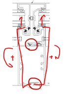
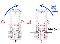
To some extent, and under the condition of symmetric load, I suspect that is probably true. I would imagine that the two sections tend to rotate in opposing directions about their shear centers and bump into one another at the compression flange (suction). Thus, they would be kind of self bracing. Not that one wants to bet the farm on such a sketchy mechanism. The fact that you don't hear any of this on a windy day leads me to believe that, for the most part, other stuff is doing the torsional bracing job most of the time.

Another thing that you have going for you under suction is that it's "loading below shear center" which tends to have a stabilizing effect.

c01.JPG
 
To some extent, and under the condition of symmetric load, I suspect that is probably true. I would imagine that the two sections tend to rotate in opposing directions about their shear centers and bump into one another at the compression flange (suction). Thus, they would be kind of self bracing. Not that one wants to bet the farm on such a sketchy mechanism. The fact that you don't hear any of this on a windy day leads me to believe that, for the most part, other stuff is doing the torsional bracing job most of the time.

Another thing that you have going for you under suction is that it's "loading below shear center" which tends to have a stabilizing effect.
Found an article that I think pretty conclusively shows some of this ("Full scale tests of aluminum mullion couples in unitized façades under wind actions"). Under positive wind loading, the glass ends up being very effective as a lateral brace for the compression flange, and even better if the glass is structurally bonded with a structural adhesive instead of just captured. Discrete or continuous clips just improve service performance and the maximum moment starts to get somewhat close to the section yield moment capacity. All good there.
Under positive wind pressure, because the mullions have different shear centers, one pushes against the other with different force and causes failure if they do not have clips. Adding a clip at midspan does not give Lb/2 (which is the common assumption), but does increase capacity. Sadly no test for continuous clipping.

If I had to guess I would say very probably having the continuous clips would add sufficient capacity to make the local flange buckling the limiting moment, instead of the LTB moment.

Schematic.jpg
 

Part and Inventory Search

Sponsor